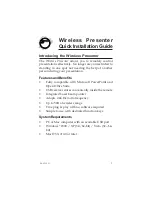
Field I/O Wiring Examples
System Components
2
Rev. 1G, Dec 2008
HawkEye™ 1600T Smart Camera Guide
2-13
Output Opto Wiring
Figure 2–10 shows the output opto wiring for isolated input.
FIGURE 2–10.
GPIO Output Opto Wiring (NPN and PNP)
Note 1: GPIO IN COM typically connected to ground.
Note 2: GPIO IN COM typically connected to Voltage.
Figure 2–11 shows the output opto wiring for isolated relay and PLC inputs.
FIGURE 2–11.
Output Opto Wiring (Relay and PLC Inputs)
NPN Sink
Signal
See Note 1
GPIO IN COM
GPIO x
GPIO OUT COM
GPIO OUT COM
GPIO x
See Note 2
GPIO IN COM
15-30V
PNP Source
15-30V
Signal
Camera
Camera
OUT COM
OUT x
15-30V
OUT COM
OUT x
GND
Input
PLC
15-30V
PLC
Relay
Camera
Camera
Summary of Contents for HawkEye 1600T
Page 1: ...HawkEye 1600T Smart Camera Guide EM 40247 1G Rev 1G Dec 2008...
Page 4: ......
Page 8: ...Contents viii HawkEye 1600T Smart Camera Guide Rev 1G Dec 2008...
Page 10: ...Preface x HawkEye 1600T Smart Camera Guide Rev 1G Dec 2008...
Page 40: ...Chapter 3 Optics Lighting 3 4 HawkEye 1600T Smart Camera Guide Rev 1G Dec 2008...
Page 48: ...Appendix A Connector Pinouts A 8 HawkEye 1600T Smart Camera Guide Rev 1G Dec 2008...
Page 54: ...Appendix B Cable Specifications B 6 HawkEye 1600T Smart Camera Guide Rev 1G Dec 2008...
Page 62: ...Appendix C Specifications C 8 HawkEye 1600T Smart Camera Guide Rev 1G Dec 2008...