micro
HAM ©
2015
All rights reserved
EDIT MODE
Built in SCREENs can be very easily customized in real time, cloned for the same layout but different
parameters, copied between sensors etc. As was written above, to each sensor up to 16 screens can be
associated, doesn't matter if they are built in, customized or cloned. You can have the same screen cloned with
same settings for main display because you like the template but you need different settings for bar graphs (for
example because you want slower movement on SSB) or for whatever reason.
To
enter
EDIT mode push briefly
EDIT
button [11]. To
exit
EDIT MODE push briefly
EDIT
button again.
In EDIT mode main display [8] shows some fields outlined. Outlined fields are parameters that can be changed,
customized. Basic and globally applicable golden rule is: “What is outlined, it can be changed”.
Outline around the parameter which fades in and out means that the parameter is
selected
and can be changed
by Rotary Knob. To move selection between parameters use ← and → SCREEN buttons.
Built-in HELP
If you are unsure what some parameter means, push the rotary knob for short help. By rotating knob while you
are in the help window, you can scroll between all available choices and read at the same time what it means or
does. Push the knob or EDIT button to register new choice and exit from help window.
We've put a lot of effort to make short help available for virtually every item possible to change. Once you
read this manual completely, built-in help system should refresh your memory and make you able to set what you
want without reaching for this manual again. Hope you find the built-in help useful.
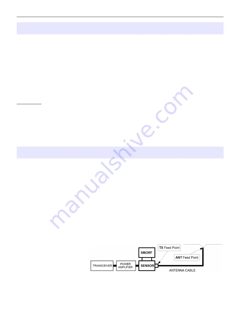
TWO POINT MEASUREMENTS, TX and ANT subscripts, - REF
When you look at most of SCREENs you certainly wonder what these
TX
and
ANT
subscripted suffixes means.
They present another unique feature of the SMΩRF called “two point measurement”.
Thanks to the calibration correction, SMΩRF provides very accurate measurements related to the outer plane of
the LOAD connector at the sensor. This point is in SMΩRF language called
TX Feed Point
and data measured
at this point are shown with TX suffix after the data type, like FWD
TX
for the forward power or SWR
TX
for Standing
Wave Ratio.
Having measured all data at the TX Feed Point, SMΩRF can mathematically work out powers and transmission
line parameters at the end of the cable where cable connects your antenna and show what happens there, how
much power is actually radiated. This point is called
ANT Feed Point
and data at this point are shown with ANT
suffix after the data type, like FWD
ANT
for the forward power or SWR
ANT
for Standing Wave Ratio. Although these
data are calculated rather than measured, SMΩRF includes precise models of over 30 commonly used coaxial
cables to choose from. Accuracy of provided results is directly related to the manufacturing differences of the
cable to its specification, accuracy of the user entered cable length and accuracy of the TX feed point
measurements. Good cable matches specifications within 5% according to cable manufacturer claims, how
accurately you measure and enter physical cable length is up to you. The
SENSOR MENU - ANTENNA
CABLES
chapter deals with antenna cables in more detail. Please note, by default SMΩRF uses lossless 50Ω
cable model for all ANT Feed Points
to avoid any confusion while you
aren't familiar with this feature. It
doesn't matter if you choose TX or
ANT Feed Point until you edit
ANTENNA CABLES table. Till than
result will be the same, providing
values of TX Feed point in both cases.
12
Summary of Contents for SMORF
Page 30: ...microHAM 2015 All rights reserved intentionally left blank 30...
Page 34: ...microHAM 2015 All rights reserved intentionally left blank 34...
Page 44: ...microHAM 2015 All rights reserved SYSTEM MENU AUX PORT intentionally left blank 44...
Page 64: ...microHAM 2015 All rights reserved 13 DATA STRUCTURE DIAGRAM 64...


