background image

micro

HAM © 

2022


All rights reserved


3 - ARXC - SOFTWARE SETUP 


After wiring it is necessary to make software setup of ARXC modules in the ARCO menu 
system. ARXC.LoRa modules have no software setup, they are set to operate together in 
factory. ARXC.MAG and ARXC.REL requires specific setup to let ARCO know how to use each 
module.


ARXC.MAG Settings 

Menu->System->ARXC.MAG window serves for magnetic sensor settings. 

ENABLE:

 Enables or disables ARCO communication with ARXC.MAG sensor.

STATUS:

 Shows current status of ARXC.MAG sensor

WAITING SENSOR RESPONSE = Sensor does not communicate to ARCO.

INIT = Temporary state during initialization and data transfer.

TURN LIMIT-TO-LIMIT = Sensor is waiting for full rotator turn. 
Turn rotator 360˚ using CW/CCW buttons.

ACTIVE = Sensor uses captured data.

SENSOR POINTS = Sensor is in user, absolute azimuth calibration state.

RESUME/FINISH LEARNING:

 When ARXC.MAG is not ARCO main azimuth sensor, button 

switches between “collecting” and “using” magnetic data to determine azimuth. While learning, 
magnetic data are continuously sampled and ARCO improves magnetic curve of the sensor.

ARXC.MAG AZI:

 Shows azimuth determined by ARXC.MAG sensor

SLIP CONTROL:

 Enables or disables background checking if azimuth of main sensor on rotator 

matches azimuth determined by ARXC.MAG sensor /- tolerance set next.  

ACCEPTED SLIP:

 Lets user know angle of antenna slippage. Angle should be used as “offset” 

for antenna #2 or  #3 for temporary use until antenna slippage is fixed. Angle can be manually 
reset 

when slippage is fixed

 and antenna is back in its original position.
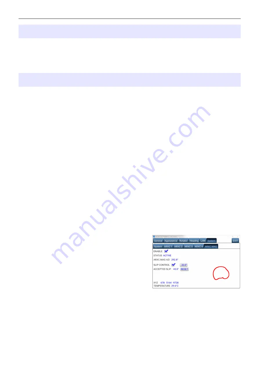
XYZ:

 Shows raw magnetic data from sensor. During 

rotator movement ARCO draws graphical magnetic data 
used for azimuth computing. Deviations from circle or 
ellipse visualizes strong magnetic interference in given 
direction as shown on picture.

TEMPERATURE:

 Shows temperature of the sensor.

  
The Menu->System->ARXC.MAG window behaves 
similarly as Menu->Heading->Calibration, 
i.e. when buttons Left or Right is pressed, the rotator motor starts to turn in given direction with 
no ramps, using speed set as CALIB SPEED in Menu->Heading->Calibration. 

In this window, the ARXC.MAG sensor is continuously polled, unlike during normal operation, 
when it is polled only when motor supply is turned on. 

9

Summary of Contents for ARXC.LoRa

Page 1: ...microHAM 2022 All rights reserved ARXC ARCO External Control Accessories ARXC REL ARXC MAG ARXC LoRa microHAM www microham com microHAM s r o Maticna 28 92401 Galanta Slovakia v1 1 2022 1...

Page 2: ...Ra 3 2 ARXC HARDWARE SETUP 4 ARXC REL addressing 4 ARXC wiring 4 3 ARXC SOFTWARE SETUP 9 ARXC MAG Settings 9 Using ARXC MAG Sensor 10 ARXC REL Settings and Use 13 DECLARATION OF CONFORMITY 17 TRADEMAR...

Page 3: ...switches mast preamplifiers or anything what is suitable to be controlled from the ARCO user interface touch screen or VNC for Internet remote control ARCO uses preset buttons for relays control and...

Page 4: ...L module each module needs to have a unique address Address is set by combination of two DIP switches according to drawing on PC board next to DIP switch It is possible to set up to 4 different addres...

Page 5: ...l consumption including powered device is 500mA limited internally by ARCO It is ample power for ARXC devices alone but if provided power reserve is not enough for powering controlled devices use D SE...

Page 6: ...microHAM 2022 All rights reserved 6 ARCO connection to single ARXC REL and ARXC MAG ARCO connection to ARXC MAG...

Page 7: ...microHAM 2022 All rights reserved 7 ARCO connection to three ARXC REL and ARXC MAG...

Page 8: ...microHAM 2022 All rights reserved 8 Wireless ARCO connection to single ARXC REL and ARXC MAG using pair of ARXC LoRa...

Page 9: ...re continuously sampled and ARCO improves magnetic curve of the sensor ARXC MAG AZI Shows azimuth determined by ARXC MAG sensor SLIP CONTROL Enables or disables background checking if azimuth of main...

Page 10: ...licking on RESUME LEARNING button Note that disabling ARXC MAG at this point deletes the ARXC MAG calibration After transition to ACTIVE state it is recommended to store ARCO configuration to one of t...

Page 11: ...ck prerequisite Now in Menu Heading Calibration turn the rotator to at least 4 evenly spaced points by 90 i e North South East West and enter azimuth for these calibration points using CUSTOM button Y...

Page 12: ...ords LED is on if the general direction of terminal block of ARXC MAG is towards North Besides that LED indicates also presence or absence of communication from ARCO if ARCO communicates with ARXC MAG...

Page 13: ...n Menu System ARXCx In 1 of N there is always exactly one relay switched on This rule is enforced even when controlling relays in the ARXC Control window and in Menu System ARXCx Individual relays can...

Page 14: ...ditable name again used as reference to this group B one of applications of BCD N group is control of Four Square type of antenna arrays so if azimuth control is enabled for BCD N the primary directio...

Page 15: ...NTENNA 2 an ARXC group with the name 1OF3 1 is selected for ANTENNA 3 the pull down is opened and displays the list of available options If ARXC group is selected instead of ANTENNA x its name is give...

Page 16: ...nsequently in this window the individual or the common set of Presets is edited B exit from this window without changing the given Preset All other buttons in this window represent possible options to...

Page 17: ...orward backward buttons instead of individual relays control and in between them the current value or if azimuth control is enabled for given group the current primary direction is displayed DECLARATI...

Reviews: