micro
HAM ©
2022
All rights reserved
2 - ARXC - HARDWARE SETUP
Installation of ARXC consists of hardware and software parts. Mechanical part of setup is to
insert rubber sealing into the slot in the module case lid. Trim its length as necessary. Sealing
might be installed by factory, in this case skip to next.
ARXC.REL can be mounted anywhere with cable grommets facing down to avoid water ingress.
Although not necessary, it is advisable to mouth box on place protected against rain, snow or
direct sunlight.
ARXC.LoRa is good to mount on place where antenna is not close to metal structures, best
when cable entry grommet is facing down and module is protected against rain, snow or direct
sunlight.
ARXC.MAG sensor has to be mounted on bottom side of antenna boom in any orientation, as
far as possible from tower and fixed by zip tights included in the package. Keep alligator clamp
screws and nuts in case you are removing it, they made of nickel plated brass, steel screws
would influence magnetic sensor functionality.
Before proceeding to software setup it is necessary to set ARXC module address (only on
ARXC.REL) and connect it to ARCO.
ARXC.REL addressing
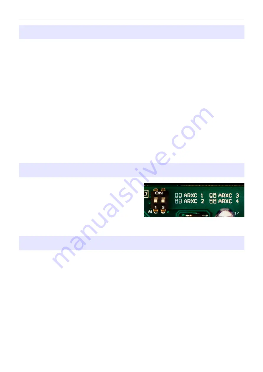
To recognize and properly control particular
ARXC.REL module, each module needs to have a
unique address. Address is set by combination of
two DIP switches according to drawing on PC board
next to DIP switch. It is possible to set up to 4
different addresses: 1 (shown on picture), 2, 3, 4.
Each ARXC.REL module has then its own setup in ARCO System menu on respective tabs
ARXC 1 – ARXC 4. ARXC.MAG has its address set internally and ARXC.LoRa has no address.
ARXC wiring
In order to control ARXC module, it must be connected to ARCO first. On ARCO, the
connection port is located at D-SENSOR connector. Communication layer is RS-485 requiring
twisted pair of wires connected to port Z (ZA and ZB pins) and two additional wires for module
power. 12VDC power is provided by ARCO at D-SENSOR port on +12V and GND pins.
If control cable between ARCO and ARXC module; or between different ARXC modules for any
reason cannot be installed, communication can be established by RF link using pair of ARXC
LoRa modules. In this case, external 12V supply must be provided on ARXC side of RF link.
Each ARXC module has a 4 pole terminal for connecting wires of the communication cable.
ZA and ZB poles serve for communication wires, +12V and GND poles serve for power. On
ARXC.REL there are two sets of terminals for simpler daisy-chain connection to additional
modules. Both terminals are connected in parallel, it is not important which one is used if you
are connecting a single module.
4


