


2015-2017 Microchip Technology Inc.
DS00001855E-page 27
USB5744
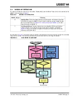
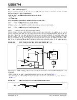
8.4.2.2
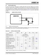
Port Power Control using Poly Fuse
When using the device with a poly fuse, there is no need for an output power control. To maintain consistency, the same
circuit will be used. A single port power control and over-current sense for each downstream port is still used from the
Hub's perspective. When disabling port power, the driver will actively drive a '0'. This will have no effect as the external
diode will isolate pin from the load. When port power is enabled, it will disable the output driver and enable the pull-up
resistor. This means that the pull-up resistor is providing 3.3 volts to the anode of the diode. If there is an over-current
situation, the poly fuse will open. This will cause the cathode of the diode to go to 0 volts. The anode of the diode will
be at 0.7 volts, and the Schmidt trigger input will register this as a low resulting in an over-current detection. The open
drain output does not interfere.
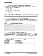
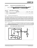
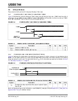
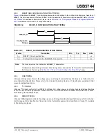
FIGURE 8-4:
DOUBLE LOW PULSE OVERCURRENT DETECTION
TABLE 8-2:
OVERCURRENT PULSE TIMING
Symbol
Description
Min
Max
Units
t
ocs_single
single low pulse assertion time
5
-
ms
t
ocs_double
double low pulse window
-
20
ms
Note:
The USB 2.0 and USB 3.1 Gen 1 bPwrOn2PwrGood descriptors must be set to 0 when using poly-fuse
mode. Refer to Microchip application note AN1903 “Configuration Options for the USB5734 and USB5744”
for details on how to change these values.
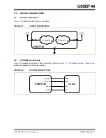
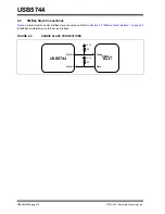
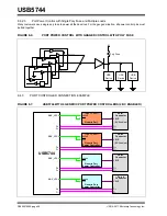
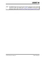
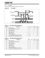
FIGURE 8-5:
PORT POWER CONTROL USING A POLY FUSE
PRT_CTLx
IS V
IL
t
ocs_double
PRT_CTLx
50k
PRTPWR
OCS
USB
Device
Pull-Up Enable
5V
Poly Fuse
FILTER


