


Page 15
Installation
surfaceCONTROL 2500
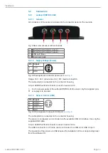
5.2.1.4 Image Data Transmission (Gigabit Ethernet)
Pin
Signal
1
Data1+
2
Data1-
3
Data2+
4
Data3+
5
Data3-
6
Data2-
7
Data4+
8
Data4-
Fig. 11 Pin assignment connector “Ethernet port”
For the image data output of the cameras via Gigabit Ethernet, the sensor has two Giga-
bit Ethernet interfaces. The sensor supports only the transmission with 1 Gbit.
8-pin, X-coded, M12 round connectors with screwed connections are used on sensor
side.
The connection and tightening of the Ethernet cable to the sensor can be done by hand
and does not require any tools. Proceed as follows for this:
Carefully insert the cable connector into the port on the sensor.
Turn the cable connector until you feel the latching of the inner groove into the corre-
sponding guide of the port.
Fig. 12 Connecting Ethernet connector to port
Tighten the cable connector.
Do not apply force when tightening.
> Damage to or destruction of the sensor
RJ45 connectors are used on the PC side.
i
Use only the Ethernet cable supplied in the scope of delivery.


