


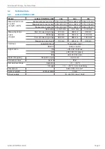


Page 14
Installation
surfaceCONTROL 2500
5.2
Connectors
5.2.1
surfaceCONTROL 2500
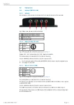
5.2.1.1 General
All connectors of the sensor are located in the connector panel on the rear side.
1
2
3
2
4
Fig. 8 Rear view of sensor with connectors
1
Ethernet port Camera 1 (green)
2
Ethernet port Camera 2 (green)
3
USB port (blue)
4
Power port (red)
5.2.1.2 Supply Voltage (Power)
Pin Signal
1
2
1
VCC
2
GND
Fig. 9 Pin assignment connector power port
Range: 18 V - 24 V (rated value 19 V) DC; maximum load 8 A
The cable shield is connected to the connector housing.
A 2-pin LEMO PushPull connector is used on sensor side.
i
For the power supply of the surfaceCONTROL 2500 sensor, only the supplied pow-
er supply is to be used.
5.2.1.3 Sensor Control (USB)
Pin Signal
1
USB D+
2
USB D-
3
USB VCC
4
GND
Fig. 10 Pin assignment connector USB port
The cable shield is connected to the connector housing.
The sensor is configured and controlled via the available USB 2.0 interface. Use only the
supplied USB cable.
A 4-pin LEMO PushPull connector is used on sensor side.
The USB-A connector on PC side can be connected to a USB 2.0 or USB 3.0 port.
The operation of the sensor via USB requires the installation of the corresponding driver
from the software CD.


