Page 16
Installation and Assembly
MSC7401 Miniature sensor controller for inductive sensors
Secondary coil +
Secondary coil -
Center tab
Shield sensor cable
Magnetic core
Plunger
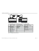
Fig. 7 Pin assignment for sensor on the terminal block X2, half bridge
Terminal block X2
Coil
Cable
1
LDR-x-CA
LVP-25-Z20-x
Connector
LDR-x-SA
Sensor cable
1
C7210-x
Secondary coil +
Pin 3
Secondary
white
1
brown
Secondary coil -
Pin 4
brown
3
blue
Center tap
Pin 2
green
4
black
Primary coil -
Pin 6
Primary
-
-
Primary coil +
Pin 5
-
-
Shield sensor cable Pin 1
-
-
Fig. 8 Table for the pin assignment for the sensor at the terminal block X2, half bridge
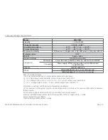
You will find the pin assignment for the terminal block in the table, see
Fig. 9
, see
Fig. 10
, see
Fig. 11
.
1) The colors and pins listed apply to MICRO-EPSILON displacement sensors.


