Page 28
Installation and Assembly
induSENSOR DTD / MSC7xxx
Wiring
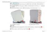
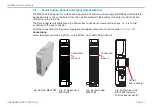
The housing must be open to connect the sensors
and wire the output and power supply cable
.
Loosen the screws.
Pass the sensor and signal cables through the cable glands.
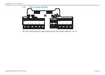
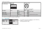
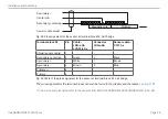
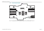
Connect the cables to the terminals according to the pin assignments.
Magnetic core
Plunger
Sec
Secondary -
Secondary
center tap
Primary -
P
Sensor cable
shield
Fig. 16 Pin assignment for the sensor at terminal block X2, full bridge
Terminal block X2
Pin
Cable
1
DTA-x-CA-x
DTA-x-CR-x
C701-x
Braid
1
DTA-x-LA-x
Solder pin
1
DTA-x-TA-x
Cable
1
DTA-xG8-x
Shield (sensor cable)
1
Shield
-
-
Shield
Secondary center tap
2
Gray
Gray
5
Gray
Sec
3
White
White
1
Black
Secondary -
4
Brown
Black
2
White
P
5
Green
Green
3
Blue
Primary -
6
Yellow
Yellow
4
Brown
Fig. 17 Table of the pin assignment for the sensor at terminal block X2, full bridge
1) The colors and pins listed refer to the sensors from MICRO-EPSILON MESSTECHNIK GmbH & Co. KG.

