Micro-Air, Inc.
Page 5
EasyTouch 2.5 Operations Manual
Rev 1.0 8/27/14
4. OVERVIEW
4.1 EasyTouch Home & Main Screen Displays
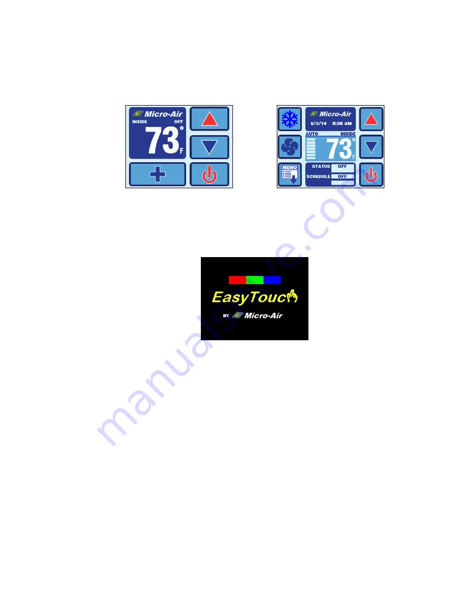
The EasyTouch Home screen shown in Figure 1 consists of large, easy to read graphics, with large
buttons for basic control functions. The Main screen shown in Figure 2 consists of smaller graphics
showing all of the controls readouts and statuses, and had more buttons for all of the control
functions.
Figure 1
– Home Screen Display
Figure 2
– Main Screen Display
4.2 EasyTouch Power-Up & Default Sleep Mode Screen Display
During power up and whenever the display enters Sleep Mode, the display shown in Figure 3 is
shown. While in Sleep mode, the graphic will move around the screen. See section 14.3 for more
information on the various Sleep Mode settings.
Figure 3
– Power-Up & Default Sleep Screen Display
5. INSTALLING THE DISPLAY PANEL
5.1 Choosing the Location
Before mounting the control panel, consider the location. The display panel’s built-in air sensor
provides excellent room-air temperature sensing when properly located and installed. The physical
location of the air sensor is shown in Figure 4
and marked with “S”. Be sure to mount the display
panel on an inside wall, slightly higher than mid-height of the cabin, in a location with freely circulating
air where it can best sense average temperature.
The display’s distance from the air conditioner must
be within the 15’ (4.5m) length of the display cable. Longer, custom cable lengths are also available.


