background image

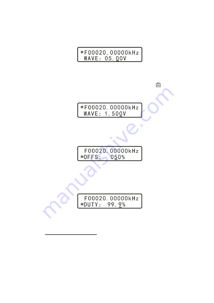
In the default range setting function mode, the maximum amplitude is

15V, and the minimum amplitude is 0.15V; the incremental step value is
0.01V (10mV).

The -20dB output attenuator may be selected by pressing the

button.

With attenuation, the output signal has a maximum value of 1.500V, the
minimum value of 0.015V, and the minimum step is 0.001V (1mV).

4.2.4

Setting CH1 voltage offset

Change the mode to bias adjustment, and move the cursor to the desired
digit, then turn the "ADJUST" knob to adjust the offset parameter.

4.2.5

Setting CH1 duty cycle

Change the mode to adjust the duty cycle, move the cursor to the desired
decimal digit, then turn the "ADJUST" knob to adjust the duty cycle pa-
rameter.

4.2.6

Adjusting phase difference between channels

Change the mode to adjust the phase, move the cursor to the desired decimal
position , then turn the "ADJUST" knob to adjust the phase parameter.

3

3

The phase difference only makes sense if CH1 and CH2 output the same frequency.

12

Summary of Contents for MHS-5200-06M

Page 1: ...DS signal generator Zhengzhou Ming Wo Electronic Technology Co Ltd Investor Road New District Zhengzhou City Henan Province No 96 Tel 0371 86106382 Fax 0371 86106382 Website www mhinstek com E mail sa...

Page 2: ...uctions 10 4 2 1 Selecting CH1 waveform 11 4 2 2 Setting CH1 frequency 11 4 2 3 Setting CH1 output amplitude 11 4 2 4 Setting CH1 voltage o set 12 4 2 5 Setting CH1 duty cycle 12 4 2 6 Adjusting phase...

Page 3: ...r damage If it is damaged or not working properly or fails performance tests please contact your dealer or man ufacturer 2 Overview 2 1 Instrument introduction MHS 5200A series instruments use large s...

Page 4: ...ion with up to 600 seconds duration Selectable output waveform sine triangle square wave rising and falling sawtooth variable duty cycle pulse plus 16 sets of arbitrary waveform customized by the user...

Page 5: ...ws development of third party applications When connected to the PC the computer can be used to control the instrument The user can edit arbitrary output waveforms and down load it to the instrument T...

Page 6: ...L digital signal wave Arbitrary Waveform Length 1024 points Sampling rate 200MSa s Waveform amplitude resolution 8bits Minimum frequency resolution 10mHz Frequency error 5 10 6 Frequency stability 1 1...

Page 7: ...s Frequency range for several selectable gate times 10s 0 1Hz 60MHz 1s 1Hz 60MHz 0 1s 10Hz 60MHz 0 01s 100Hz 60MHz Input voltage range 0 5Vp p 20Vp p Counting range 0 4294967295 Counting Manual Positi...

Page 8: ...face is described in Figure 1 1 LCD1602 LCD 7 CH2 output connector 2 Status Indicator 8 Power switch 3 Operation buttons 9 5VDC power input 4 Rotary knob selector 10 USB connector 5 Ext In input conne...

Page 9: ...rmation button also changes the parameter in the current menu selection Channel selector Channel setting re ected by CH1 CH2 LED indicator Focus select between the rst and second display line as indi...

Page 10: ...startup the instrument enables the output and activates the front panel user interface 4 2 Operating instructions This section will detail how to operate the instrument using front panel keys the rota...

Page 11: ...e manufacturer Each of those arbitrary 16 waveforms can also be downloaded from the connected PC host by the user 1 4 2 2 Setting CH1 frequency When the A indicator is in the rst line use the left rig...

Page 12: ...e the mode to bias adjustment and move the cursor to the desired digit then turn the ADJUST knob to adjust the o set parameter 4 2 5 Setting CH1 duty cycle Change the mode to adjust the duty cycle mov...

Page 13: ...OFF with the button When the tracking function is turned on output frequency of channel CH2 automatically tracks the frequency of channel CH1 Also if CH1 and CH2 amplitude is the same before turning...

Page 14: ...TY DUTY duty cycle percent Proceed to gate time selection menu and choose one of available gate times 10s 1s 0 1s or 0 01s Di erent gate times trade o frequency measurement accuracy and measurement sp...

Page 15: ...4 2 12 Parameter storage and loading To save parameters for later use select the parameter save function then rotate ADJUST knob to adjust the save location This instru ment has a total of 10 paramete...

Page 16: ...e chemi cals and other unsafe items to be placed on the surface of the instru ment so as not to cause damage to the instrument 6 The instrument is a fragile and sensitive electronic equipment do not s...

Page 17: ...ompany will repair or replace equipment selected according to the situation For service please send the product to the company The following conditions are not covered under warranty User operation or...

Page 18: ...erial interface Figure 4 MHS 5200A main circuit board B MHS 5200A serial protocol This is a copy of Al Williams work at https github com wd5gnr mhs5200a The manufacturer claims that the communication...

Page 19: ...odel r0c52A Start up r1c Read Prod r1c323 Start up r2c Read FW 3 23 r2c015 Start up sXf Write frequency for channel X ok rXf Read frequency for channel X rXfNNNNNNNN sXwN Select waveform N for channel...

Page 20: ...NN s4f Set Sweep End ok r4f Read Sweep End r4fNNNNNNNN NN s7bN Set Line log ok N 1 for lin 0 for log r7b Read line log r7bN s8bN Start Stop sweep ok N 0 for stop 1 for start r8b Read sweep state rb8N...

Page 21: ...ounter mode r6b Read run state r6bN s5b1 Reset counter ok r5b Read reset status r5bN Functions still unknown Reading back arbitrary storage if even possible Setting or loading stored setups Sweep time...

Reviews: