


3
CHAPTER 1
This chapter will help you understand the issues involved
in planning an RMS network for your system design. Type
of hardware, number of loudspeakers and their layout are
all crucial to setting up a fast, trouble-free RMS network.
SYSTEM REQUIREMENTS
To ensure that the RMS monitoring system runs smoothly,
the following system specifications are required:
■
Windows® 98SE/NT 4.0 (SP5)/2000/XP™ (SP1) or
higher
■
Pentium® III processor or higher (350 MHz min., 500+
MHz recommended
■
64 MB RAM min. for 98SE/NT, 128+ recommended;
128 MB RAM min. for 2000/XP, 256+ recommended
■
4 MB video card or higher (800 x 600 min. resolution)
■
At least 50 MB free hard drive space.
■
For a large network: 20 MB/s sustained transfer rate
with less than 8 ms average seek time
■
One open full-size, 32-bit (standard) PCI slot or Type II
PC Card (PCMCIA) card slot
CAUTION:
A half-size PCI slot will not
accommodate the Network Interface Card
used by RMS. Ensure that you have a full-sized,
standard PCI slot available.
NOTE:
If you are running the RMS
application on a laptop computer, a
PCMCIA Type II port is required.
TIP:
RMS is designed to multitask with
other Windows applications. However,
because of the large amount of data processing
and monitoring that must occur in real-time, Meyer
Sound recommends running RMS as a stand-alone
application (no other applications running). If you
experience problems running RMS in conjunction
with other Windows applications, close the other
programs to determine if the problem is due to a
conflict with those applications.
If you do decide to multitask RMS with other
applications, please be aware of the following:
■
Avoid operations that are CPU intensive. For
example, audio (signal) processing, spectrum/
frequency analyzers, large file copying, and
playing music and video files.
■
Avoid operations that are network intensive (i.e.
those that heavily use the Ethernet port). For
example, streaming audio/video, large network file
transfers, Web/Internet browsing of multimedia
content, and heavy use of email or instant
messaging.
HARDWARE COMPONENTS
RMS ships with a number of different hardware options
depending on how you decide to configure your
network. This section will walk you through the different
components for a twisted pair versus an Ethernet-based
network, as well as the components common to both
types of networks.
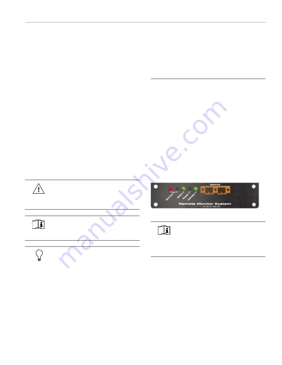
The RMS User Panel
You must have an interface on the loudspeaker before
you connect to it through a network. All Meyer Sound
self-powered loudspeakers (with the exception of the
HD-1/2, UPL-1/2 and HM-1S) can be equipped with an
RMS communications module. The module's user panel is
shown in Figure 1.1.
Figure 1.1. The RMS communication module’s user panel
NOTE:
All M Series loudspeakers are fitted
with the RMS communications module
as standard. The RMS communications module
is available as an option for other self-powered
Meyer Sound loudspeakers.
The user panel is straightforward, with three LEDs and two
buttons. Their functions are as follows:
Network Connectors
Two Weidmuller locking network connectors enable data
transmission to and from the network. The connectors are
bi-directional – able to both transmit and receive network
data.
Service LED (Red)
When blinking once every two seconds, the Service LED
indicates that the communications module is operational,
but the loudspeaker is not installed on the network. When
the loudspeaker has been installed on the network the
Service LED will be not be lit, while the Activity LED will
CHAPTER 1: PLANNING AND DESIGNING FOR RMS
Summary of Contents for RMS 4.5
Page 1: ...USER GUIDE RMS 4 5...
Page 28: ...24 CHAPTER 2...
Page 56: ...52 APPENDIX A...
Page 60: ...56 APPENDIX B...
Page 62: ......
Page 63: ......
Page 64: ...2004 Meyer Sound Laboratories Inc 05 033 302 02 A...


