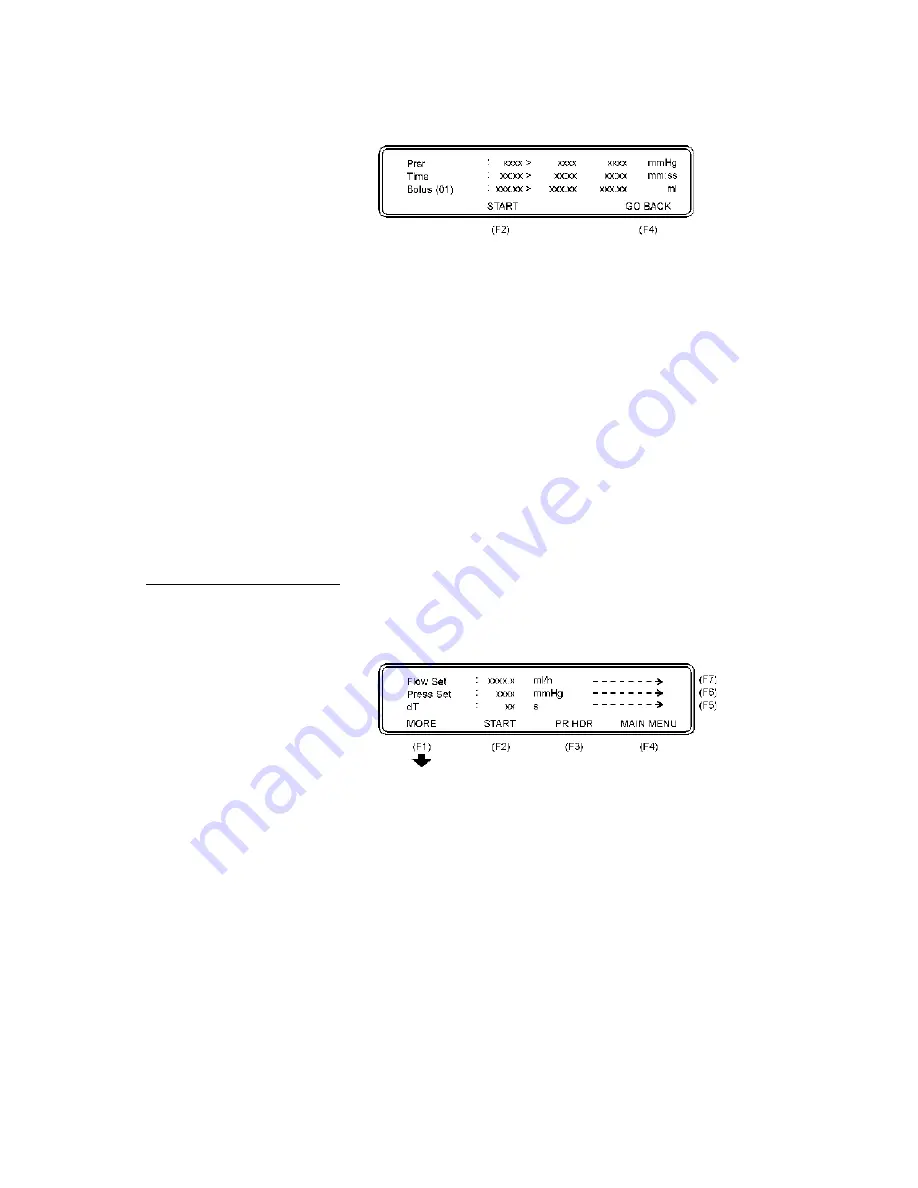
The following parameters will then be displayed:
Prsr:
The pressure in the connction tube. Measurement results
display: max. value > instantaneous measured value >
mean value in mmHg.
Note:
For multiple measurements,
max. measured value > last measured value > mean
value are displayed.
Time:
The time from test start until alarm activation. Measure-
ment results display: max. time > elapsed time > mean
time in minutes/seconds.
Bolus:
The volume expansion within the tube when the infusion
pump alarm activates. Measurement results display: max.
bolus > last executed calculation after STOP is pressed >
mean bolus in milliliters.
Note:
Maximum bolus volume to
be measured with a standard QA-IDS is about 1.7
milliliters.
7. A new measurement in a series is initiated by just pressing
START (F2)
to start test.
According to the IEC an occlusion test should be run with different
settings of flow rate and, if the pump has a programmable occlusion
pressure alarm, different alarm settings are recommended.
4.4 Infusion Flow Rate
and Volume Testing
1. Press
Flow measurement (F6)
in from the Main Menu and the
display will show the
Flow Measurement Setup 1
Menu.
The following parameters are displayed:
Flow Set:
This value is the preset value of the infusion pump. All
error calculations of the flow measurement are related to
this value. If the Flow Set value is not entered correctly,
this may cause a poor presentation with incorrect overall
errors.
Press Set:
This function gives the possibility to enter + (positive) or
- (negative) backpressure into the system. Operation
range is from -200 to +600 mmHg.
dT:
Interrogation time, or time between two measurements.
Average value during the test interval is displayed. Rec-
ommended dT from IEC is 30 sec, and this is the mini-
mum value to be selected on the QA-IDS. Maximum dT
is 600 sec. or 10 minutes. Default value is 30 sec.
26
Summary of Contents for QA-IDS
Page 1: ...1 Q A ID S U s e r S e r v i c e M a n u a l Q A I D S I n f u s io n P u m p T e s t e r...
Page 6: ...This page intentionally left blank 6...
Page 12: ...This page intentionally left blank 12...
Page 32: ...This page intentionally left blank 32...
Page 38: ...This page intentionally left blank 38...
Page 40: ...This page intentionally left blank 40...
Page 41: ...Processor board Component Location 41...
Page 42: ...6 10 1 Processor board Schematic Diagram 1 42...
Page 43: ...6 10 2 Processor board Schematic Diagram 2 Digital Part 43...
Page 44: ...6 10 3 Processor board Schematic Diagram 3 CPU 44...
Page 45: ...6 10 4 Processor board Schematic Diagram 4 Memory 45...
Page 46: ...6 10 5 Processor board Schematic Diagram 5 RS232C and Printer 46...
Page 47: ...6 10 6 Processor board Schematic Diagram 6 Digital Outputs 47...
Page 48: ...6 10 7 Processor board Schematic Diagram 7 Digital Inputs 48...
Page 49: ...6 10 8 Processor board Schematic Diagram 8 A D 49...
Page 50: ...6 10 9 Processor board Schematic Diagram 9 Stepper Motor and Drivers 50...
Page 51: ...6 10 10 Processor board Schematic Diagram 10 Pressure Sensor and Temper ature 51...
Page 52: ...52...
Page 53: ...6 10 11 Processor board Schematic Diagram 11 Main Part 53...
Page 54: ...54...
Page 55: ...6 10 12 Processor board Schematic Diagram 12 Keyboard Pressure Sensor and Pump Index 55...
Page 56: ...56...
Page 57: ...6 10 13 This page intentionally left blank 57...
Page 59: ...This page intentionally left blank 59...
Page 61: ...This page intentionally left blank 61...
Page 62: ...62...


