•
Start the infusion pump with a high flow rate. Keep the
QA-IDS working until there is no more air in the tubes.
Timeout is max. 10 minutes.
•
Press
GO BACK (F1)
to return to the main menu.
4.3 Occlusion Pressure/
Bolus Volume Testing
To protect the patient, an infusion device should include an occlu-
sion pressure alarm. This alarm should activate if the pressure inside
the administration set exceeds preset levels. Since an occlusion with
built up pressure also distends the administration line, an excess vol-
ume of liquid is stored in the line. This is the
Bolus volume
, which is
a discrete quantity of liquid delivered in a short time, and is not in-
tended to form a part of the continuous flow output. Such uncon-
trolled volume may also be a risk to the patient, and must be mea-
sured for the infusion pump.
1. Prime the QA-IDS as per paragraph 4.2.2 above.
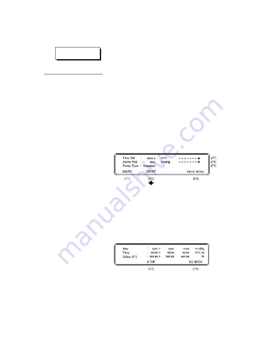
2. Press
Occlusion Test (F5)
in the Main Menu and the fol-
lowing display will appear:
3. Press
Flow Set (F7)
to select an intermediate flow rate on
the infusion device.
4. Press
Alarm Prsr (F6)
to enter a preset pump value on
pumps having programmable occlusion alarm settings.
5. Press
Pump Type (F5)
and select between the two options:
Standard
or
Reversing
.
6. Start the infusion, and simultaneously press
START (F2)
to
start the Occlusion Test, and the following display will ap-
pear.
During the test, the pressure (
Prsr
) in the administration set and
elapsed time will be displayed. When the Occlusion Alarm on
the infusion pump is activated, press
STOP (F2)
to stop the
test, and the following display will appear.
25
CAUTION
Prime the unit properly.
Summary of Contents for QA-IDS
Page 1: ...1 Q A ID S U s e r S e r v i c e M a n u a l Q A I D S I n f u s io n P u m p T e s t e r...
Page 6: ...This page intentionally left blank 6...
Page 12: ...This page intentionally left blank 12...
Page 32: ...This page intentionally left blank 32...
Page 38: ...This page intentionally left blank 38...
Page 40: ...This page intentionally left blank 40...
Page 41: ...Processor board Component Location 41...
Page 42: ...6 10 1 Processor board Schematic Diagram 1 42...
Page 43: ...6 10 2 Processor board Schematic Diagram 2 Digital Part 43...
Page 44: ...6 10 3 Processor board Schematic Diagram 3 CPU 44...
Page 45: ...6 10 4 Processor board Schematic Diagram 4 Memory 45...
Page 46: ...6 10 5 Processor board Schematic Diagram 5 RS232C and Printer 46...
Page 47: ...6 10 6 Processor board Schematic Diagram 6 Digital Outputs 47...
Page 48: ...6 10 7 Processor board Schematic Diagram 7 Digital Inputs 48...
Page 49: ...6 10 8 Processor board Schematic Diagram 8 A D 49...
Page 50: ...6 10 9 Processor board Schematic Diagram 9 Stepper Motor and Drivers 50...
Page 51: ...6 10 10 Processor board Schematic Diagram 10 Pressure Sensor and Temper ature 51...
Page 52: ...52...
Page 53: ...6 10 11 Processor board Schematic Diagram 11 Main Part 53...
Page 54: ...54...
Page 55: ...6 10 12 Processor board Schematic Diagram 12 Keyboard Pressure Sensor and Pump Index 55...
Page 56: ...56...
Page 57: ...6 10 13 This page intentionally left blank 57...
Page 59: ...This page intentionally left blank 59...
Page 61: ...This page intentionally left blank 61...
Page 62: ...62...


