background image


54 

S

CALE 

O

PERATION 


S

ECURITY 

S

EAL 

I

NSTALLATION  


The certification of the weighing mechanism of the scale version of this scanner is subject to federal, state and local 
Weights and Measures statutes and regulations and can only be performed by authorized government agencies 
and/or their duly registered agents. Each time the scale or weighing mechanism is calibrated, it should be properly 
sealed with a paper seal or a wire seal prior to being placed into service in commerce.  
 
It is the responsibility of the owner of the scale to confirm compliance with the relevant Weights and Measures statutes 
and regulations applicable in your area by checking with the appropriate government agency before placing a newly 
calibrated unit into service or removing any official seals. 
 
Type of seal to be used will depend on the guidelines specified by the local Weights and Measures authorities.  

 
The security seal must only be installed if there were no errors during the scale calibration verification tests.   
 

Pressure Sensitive Security Seal 


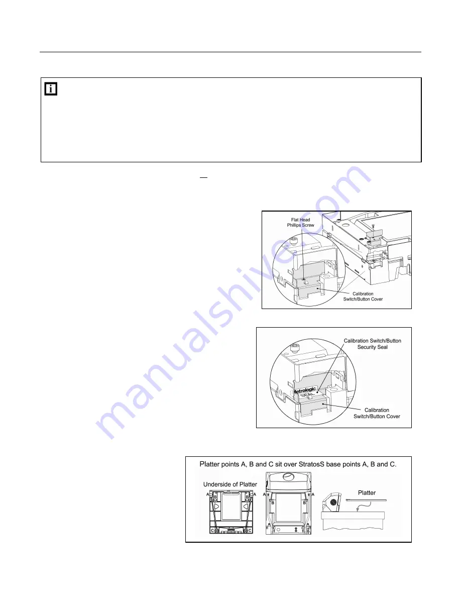
1.  Temporarily remove the platter and place it in a safe location.  
 
2.  Reinstall the calibration switch/button cover. 


3.  Apply the calibration security seal over the switch cover. 


4.  Reinstall the platter.  


Figure 63.  Calibration Switch/Button Cover

Figure 64.  Calibration Switch/Button Security Seal Placement

Figure 65.  Platter Installation


Summary of Contents for StratosS MS2220

Page 1: ...METROLOGIC INSTRUMENTS INC MS2220 StratosS Scanner Avery Scale Installation and User s Guide...

Page 2: ...rior written consent except by reviewer who may quote brief passages in a review or provided for in the Copyright Act of 1976 Trademarks Metrologic is a registered trademark of Metrologic Instruments...

Page 3: ...0 Caution and Serial Number Labels 11 INSTALLATION Quick Installation Outline 12 Site Requirements 12 Vertical Clearance 12 Ventilation and Spacing 12 Service Access 13 Power Installation 13 Checkout...

Page 4: ...ols Required 42 Scale Calibration Methods 42 Priming the Scale for Calibration lbs kg 43 Scale Calibration Procedure lbs kg with Remote Display 44 Bar Code Calibration Procedure without Remote Display...

Page 5: ...E OF CONTENTS SCANNER AND CABLE TERMINATIONS Scanner Pinout Connections 69 Cable Connector Configurations 71 REGULATORY COMPLIANCE Safety 73 EMC 74 Weights Measures 75 LIMITED WARRANTY 76 PATENTS 77 I...

Page 6: ...v...

Page 7: ...Upgrade latest software enhancements on site Powered Aux Port Connect hand held scanner for large or bulky items Integrated Scale Factory integrated field upgradeable Avery scale Loud Speaker 3 volum...

Page 8: ...mmunication Cable Straight 4 0 m 13 Cord Locking 12V Plus Power Type A 57 57000x N 3 Dual Interface Cable Straight 3 7 m 12 Cord with Short Strain Relief 57 57008x N 3 Aux Program Cable Straight 2 3 m...

Page 9: ...00248 Remote Scale Display for use with MS2000 lb Scanner Scales 46 00249 Remote Scale Display for use with MS2000 kg Scanner Scales Figure 1 Optional Remote Scale Display Dimensions Specifications ar...

Page 10: ...ation 46 00232 Vertical Window 46 00233 Diamonex Platter Full Size 46 00296 Diamonex Platter Full Size with Product Weight Roll Bar Platter Lift Handle 46 00235 Sapphire Platter Full Size 46 00297 Sap...

Page 11: ...eplacement platter or the vertical window frame PLATTER REMOVAL No hardware or tools are required to remove the platter see Figure 5 Refer to the Maintenance section of this manual for additional info...

Page 12: ...5 0 mil Scan Zone 360 Decode Capability All Standard 1 D Bar Codes RSS 14 RSS Expanded and RSS 14 Limited Bar Codes System Interfaces RS232 Aux RS232 IBM468x 469x USB and OCIA Print Contrast 35 Minimu...

Page 13: ...11 9 Watts Standby Power 3 25 Watts Operating Current 1 5A 5 2V 3A 12V Standby Current 44 A 5 2V 08A 12V DC Transformers Class II 5 2VDC 2A 12VDC 1A For Regulatory Compliance Information refer to page...

Page 14: ...8 BASE MODEL CHARACTERISTICS MS2220 Scanner Avery Scale Components Figure 7 MS2220 Components...

Page 15: ...aled Calibration Switch Button Cover Located Under Platter On a fully installed unit the calibration switch cover should be sealed with a lead wire or paper seal This seal indicates the appropriate Fe...

Page 16: ...10 BASE MODEL CHARACTERISTICS MS2220 Scanner Avery Scale Dimensions Figure 8 MS2220 Dimensions Specifications are subject to change without notice Connector Panel Figure 9 MS2220 Connector Panel...

Page 17: ...maintain compliance with applicable standards all circuits connected to the scanner must meet the requirements for SELV Safety Extra Low Voltage according to EN IEC 60950 1 To maintain compliance with...

Page 18: ...cal Clearance A minimum clearance height of 5 25 from the checkout counter surface is needed for the vertical hood on all of the scanner models Ventilation and Spacing All StratosS models have a die c...

Page 19: ...this manual Metrologic recommends using a switched AC outlet The switch should be located on the operator s side of the checkout counter in close proximity to the StratosS to facilitate calibration a...

Page 20: ...pping the bottom of the unit on both sides Important Do not lift the unit out of the box by gripping the sides of the platter 4 Carefully remove the shipping foam around the unit Important Do not turn...

Page 21: ...d shipping hardware These items must be reinstalled if the unit is going to be shipped INSTALLING THE UNIT IN THE COUNTER Before starting to mount the StratosS determine the scanner s orientation in r...

Page 22: ...16 INSTALLATION INSTALLING THE UNIT IN THE COUNTER MS2220 Mounting Diagram Figure 16 MS2220 Mounting Diagram Specifications are subject to change without notice...

Page 23: ...te communication cables Skip to step 6 for a single cable interface where the scale and scanner connect to the host with a single cable 4 Plug the dual interface cable MLPN 57 57000x N 3 into the 10 p...

Page 24: ...scan the recall defaults bar code first Refer to the MS2xxx Stratos Series Configuration Addendum MLPN 00 02034x for scale dual cable and single cable configuration bar codes xx Specifies internation...

Page 25: ...software driver and correct configuration setting are also required for proper communication to occur Steps 4 and 5 are for dual cable interfaces where the scale and the scanner connect to the host wi...

Page 26: ...Cable Scanner Configuration Bar Codes IBM OEM Full Speed USB Communication Defaults and IBM OEM Full Speed USB Protocols FOR USB SERIAL EMULATION MODE OR KEYBOARD EMULATION MODE ONLY These features ca...

Page 27: ...SPEED USB xx Specifies international connection See the Base Kit Components and Optional Accessories section of this guide for a complete listing See Power Source caution statement located on page 11...

Page 28: ...ct configuration settings are also required for proper communication to occur Steps 4 and 5 are for dual cable interfaces where the scale and the scanner connect to the host with their own separate co...

Page 29: ...lity IBM 3 rd Generation 46xx For Dual Cable Applications The IBM 3 rd Generation 46xx and IBM OEM Full Speed USB bar code is located in the MS2xxx Stratos Series Configuration Addendum MLPN 00 02034x...

Page 30: ...ar at the host device A software driver and correct configuration settings are also required for proper communication to occur Steps 4 and 5 are for dual cable interfaces where the scale and the scann...

Page 31: ...ling and setting OCIA parameters Refer to the MS2xxx Stratos Series Configuration Addendum MLPN 00 02034x for scale dual cable and single cable configuration bar codes xx Specifies international conne...

Page 32: ...dary scanner see figure on page 27 3 Connect the angled end of the RS232 AUX cable MLPN 57 57099x 3 into the 10 pin socket labeled Aux RS232 In on the bottom of the StratosS Important The StratosS ser...

Page 33: ...ATION CABLE INSTALLATION SECONDARY METROLOGIC SCANNER See Aux power notes on page 26 See Power Source caution statement located on page 11 of this manual Figure 21 Secondary Scanner Cable Installation...

Page 34: ...6 set to ON All StratosS models have a connector labeled EAS In on the bottom of the unit Metrologic has an optional EAS cable MLPN 52 52511x available for purchase for connection between the Checkpoi...

Page 35: ...29 SCANNER OPERATION SCAN ZONE Figure 24 Checker Side 13 mil Figure 25 Horizontal Left Right 13 mil Specifications are subject to change without notice...

Page 36: ...30 SCANNER OPERATION SCAN ZONE Figure 26 Horizontal Direct 13 mil Figure 27 Vertical Direct 13 mil Specifications are subject to change without notice...

Page 37: ...etected by the IR in the activation area shown below will cause the scanner to exit the power save mode The motor will restart automatically and the laser will turn back on preparing the scanner for b...

Page 38: ...one This is a failure indicator Refer to failure modes on page 34 Three Beeps during operation When placing the scanner in configuration mode the white LED will flash while the scanner simultaneously...

Page 39: ...h and the scanner will beep once If the white LED does not flash or the scanner does not beep once then the bar code has not been successfully read Steady White and Blue After a successful scan the sc...

Page 40: ...experienced a motor subsystem failure The scanner will try up to 3 times to correct the failure condition If the motor subsystem continues to fail that subsystem horizontal or vertical will be shut do...

Page 41: ...M ERROR The scanner s software program is failing Return the unit for repair 04 INTERFACE ERROR After power up and any application exit e g MetroSet etc the scanner checks the interface hardware with...

Page 42: ...gged into the Scale RS232 to Host port If there is a disconnected cable it may be causing the communication error If there is still no communication between the scanner and scale return the unit to au...

Page 43: ...set point in memory Have the unit checked at an authorized service center 29 LASER 3 LEFT HORIZONTAL UNDERCURRENT WARNING The laser in the left vertical scanning subsystem is drawing too little curren...

Page 44: ...Any movement detected by the IR will wake the scanner from the power save mode see Figure 28 on page 31 This mode s wake time is slightly longer due to the motor s need to restart 4 Dual Action Power...

Page 45: ...tone is also selectable 9 9 9 9 7 4 Next Volume The Multi Function Button Figure 31 The Multi Function Button Changing the Beeper Volume A short 3 second depression and the beeper volume will change T...

Page 46: ...s of the types of tests performed at power up 1 Memory tests 2 Hardware setup tests 3 Motor tests 4 Laser tests 5 Configuration tests 6 Interface tests 7 Scale tests These tests are also performed on...

Page 47: ...can be re zeroed by pressing the scale zeroing button on either the unit or on the remote display stand When the scale is at zero the amber LED will be illuminated Figure 35 The scale zero button on s...

Page 48: ...confirm compliance with the relevant Weights and Measures statutes and regulations applicable in your area by checking with the appropriate government agency before placing a newly calibrated unit in...

Page 49: ...ale 1 Check the platter to ensure that nothing is interfering with its freedom to move Assure that no debris is present from daily use of the scanner scale if it has been in service 2 Apply power to t...

Page 50: ...y calibrated unit into service or removing any official seals 2 If this is a currently installed scanner scale in need of calibration cut and remove the calibration switch cover seal If this is a new...

Page 51: ...Mode See Power Source caution statement located on page 11 of this manual 5 Enter calibration mode The remote display will flash all of the characters available see illustration below Press the right...

Page 52: ...is no load on the scale platter Figure 44 9 Place a half load 15 00 lbs or 7 500 kg on the center of the scale platter then press the right arrow button Figure 45 10 Add an additional half load 15 00...

Page 53: ...n mode Press and hold the test button for at least 3 seconds then release With no load on the scale the display should read 0 00 lb or 0 000 kg Figure 49 14 The unit s calibration must now be verified...

Page 54: ...of the owner of the scale to confirm compliance with the relevant Weights and Measures statutes and regulations applicable in your area by checking with the appropriate government agency before placin...

Page 55: ...statement located on page 11 of this manual 5 Reinstall the platter and power up the unit Figure 53 Platter Installation and Power Up 6 Enter bar code calibration mode Use the vertical window to scan...

Page 56: ...that the Cal 1 value has been stored Figure 55 9 Place a half load on the center of the scale platter The white LEDs will blink twice periodically Wait for scale stability and then press the beeper v...

Page 57: ...es periodically Wait for scale stability and then press the beeper volume switch once The beeper will beep 5 times indicating that the Cal 5 value has been stored Figure 59 13 Calibration is now compl...

Page 58: ...lbs Shift Test 1 Ensure there is no load on the scale platter and verify the remote display reads 0 00 lbs 2 Place a 15 00 lb weight on the scale platter in the center of zone A see diagram and verif...

Page 59: ...and verify the display reads 0 000 kg Shift Test 1 Ensure there is no load on the scale platter and verify the remote display reads 0 000 kg 2 Place a 7 500 kg weight on the scale platter in the cente...

Page 60: ...easures statutes and regulations applicable in your area by checking with the appropriate government agency before placing a newly calibrated unit into service or removing any official seals Type of s...

Page 61: ...re through the hole in the tab that protrudes through the calibration switch button cover 5 Continue to thread the wire through the wire lock at the other end forming a loop see Figure 66 6 Crimp the...

Page 62: ...56 MAINTENANCE HORIZONTAL SCAN WINDOW REPLACEMENT Figure 67 Platter Horizontal Scan Window Replacement See replacement parts on page 4...

Page 63: ...l output windows will need occasional cleaning For the glass window 1 Spray glass cleaner onto lint free non abrasive cleaning cloth 2 Gently wipe the scanner window For the inner plastic window 1 Use...

Page 64: ...ot function During power up the unit razzes once and the blue LED flashes A VLD failure Contact a Metrologic service representative During power up the unit razzes twice and both LEDs flash Scanner mo...

Page 65: ...nter and or the printer settings could be the problem Check the print mode or change the printer settings For example change to econo mode or high speed The unit is trying to scan a particular symbolo...

Page 66: ...be added to the transmitted output Add some intercharacter delay to the transmitted output by using the MetroSelect Configuration Guide MLPN 00 02407x Aux Port Operation With Any Interface The seconda...

Page 67: ...tion software and the scanner configuration match If the application does not support RS232 scanners a software wedge program that will take RS232 data and place it into a keyboard buffer may be neede...

Page 68: ...9 Code 128 9 9 9 9 Code 93 9 9 9 9 Codabar 9 9 9 9 Interleaved 2 of 5 ITF 9 9 9 9 MOD 10 Check on ITF 9 9 9 9 Code 11 9 9 9 9 Code 39 9 9 9 9 Full ASCII Code 39 9 9 9 9 MOD 43 CD on Code 39 9 9 9 9 T...

Page 69: ...Tone on Timeout 9 9 9 9 Three Beeps on Timeout 9 9 9 9 No Beeps on Timeout 9 9 9 9 Fast Beep 9 9 9 9 Beep Twice on Supplements 9 9 9 9 No Beeps on Timeout 9 9 9 9 5 Retries Before Timeout 9 9 9 9 Time...

Page 70: ...Check Digit 9 9 9 9 UPC A Enable 9 9 9 9 Convert UPC A to EAN 13 9 9 9 9 Transmit UPC A Check Digit 9 9 9 9 Transmit UPC A Number System 9 9 9 9 Transmit UPC A Manufacturers ID 9 9 9 9 Transmit UPC A...

Page 71: ...9600 9 8 Data Bits 9 7 Data Bits 9 Stop Bits 2 9 RTS CTS Enabled 9 Message RTS 9 Character RTS 9 ACK NAK 9 O N Handshaking 9 Host Bell Cancel 9 Xon Xoff 9 No Transmit Without DTR Present 9 French PC T...

Page 72: ...Sets Multiple Selections 9 9 Configurable Prefix for Code Types 9 9 Configurable Suffix for Code Types 9 9 Configurable Code Length Locks 7 avail 9 9 9 Code Selects 7 avail 9 9 9 Transmit High Priori...

Page 73: ...nd to ISBN 9 9 9 9 Bookland 979 Supplements 9 9 9 9 Convert 979 to ISBN 9 9 9 9 Convert 290 to ISBN 9 9 9 9 Reformat ISBN 9 9 9 9 Add EAN Article ID 9 9 9 9 Transmit ISBN EAN Check Digit 9 9 9 9 977 S...

Page 74: ...Parity none 9 9 9 9 Aux Data Bits 8 9 9 9 9 Aux Stop Bits 1 9 9 9 9 Aux Character RTS 9 9 9 9 Aux Message RTS 9 9 9 9 Aux Ack Nak 9 9 9 9 Aux Xon Xoff 9 9 9 9 Aux D E Commands 9 9 9 9 Aux M O Command...

Page 75: ...12VDC 2 EAS Out 2 RS232 Receive Input 2 Ground 3 RS232 Transmit Output 3 5 2VDC 4 RS232 RTS In 5 RS232 CTS Out 6 No Connect 7 No Connect 8 No Connect 9 5V Out 10 No Connect Scale RS232 to Host Scale...

Page 76: ...232 Interface 8 DSR 9 IBM B 9 Reserved for IBM 46xx Interface 10 IBM A 10 Reserved for IBM 46xx Interface Scanner to Host OCIA Scanner to Host USB Pin Function Pin Function 1 Signal Ground 1 Signal Gr...

Page 77: ...LPN 57 57227x N 3 Pin Function 1 PC 5V USB 2 D 3 D 4 Ground Locking Type A 57 57227x N 3 Non Locking Type A 57 57201x N 3 IBM 46xx Cable MLPN 57 57212x N 3 Pin Function 1 Signal Ground 2 IBM A 3 IBM B...

Page 78: ...Signal Ground 2 RS232 from Aux Secondary Scanner 3 RS232 to Aux Secondary Scanner 4 RTS from Aux Secondary Scanner 5 CTS to Aux Secondary Scanner 6 8 No Connect 9 5VDC Transformer Direct 10 Shield Gr...

Page 79: ...lient ne doit en aucun cas essayer d entretenir lui m me le scanner ou le laser Ne regardez jamais directement le rayon laser m me si vous croyez que le scanner est inactif N ouvrez jamais le scanner...

Page 80: ...ions to this equipment could void the user s authority to operate this device This device complies with part 15 of the FCC Rules Operation is subject to the following two conditions 1 This device may...

Page 81: ...erence in a residential installation This equipment generates uses and can radiate radio frequency energy and if not installed and used in accordance with the instructions may cause harmful interferen...

Page 82: ...r accident nor any damage due to use or misuse produced from integration of the Product into any mechanical electrical or computer system The warranty is void if the case of Product is opened by anyon...

Page 83: ...r by implication estoppel or otherwise under any METROLOGIC or third party intellectual property rights whether or not such third party rights are licensed to METROLOGIC including any third party pate...

Page 84: ...codes 35 36 37 F failure error codes 35 37 indicator 32 modes 32 34 finger recess 5 full service access mode 45 function 58 65 66 67 69 72 G ground 69 72 H host 33 40 58 61 62 68 I IBM 46xx 62 68 indi...

Page 85: ...5 specifications 6 7 storage 7 switch 9 28 cover 44 48 54 T test 3 40 42 55 button 47 tone 32 39 See button T transformer see power troubleshooting 58 61 U unit of measure 52 53 USB 62 68 V ventilatio...

Page 86: ......

Page 87: ......

Page 88: ...December 2006 Printed in the USA 0 0 0 2 0 3 5 C...

Reviews: