background image

OmegaPATPlus / BetaPATPlus                                         Other instrument operations 


76 

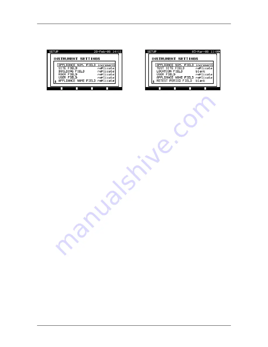
From the 

Main menu

, select 

Setup

 and then select 

Instrument settings 

by using 

¿


and 

À

 cursor keys and press ENTER key to confirm. The 

Instrument settings 

submenu

 will be displayed. 


Aus/ NZ model 


UK model 


Instrument settings menu 

 
The following data can be controlled between tests: 


UK model 

Aus/ NZ model 

Ì

 appliance 

number, 

Ì

 test 

site, 

Ì

 location, 

Ì

 user, 

Ì

 appliance 

name, 

Ì

 retest 

period 

Ì

 repairing 

code, 

Ì

 comments, 

Ì

 barcode 

system. 

Ì

 appliance 

number, 

Ì

 site, 

Ì

 building, 

Ì

 room, 

Ì

 user, 

Ì

 appliance 

name, 

Ì

 retest 

period, 

Ì

 repairing 

code, 

Ì

 comments, 

Ì

 barcode 

system, 

Ì

  second tag manipulation. 


By using 

¿

 and 

À

 cursor keys select the item whose parameter you want to change 

and press ENTER key to confirm. Use 

¿

 and 

À

 cursor keys again to set parameter to 

your needs. Press F1 function key to confirm. To restore last used setting for selected 
item press F2 key. 
In general, the 

blank

 and 

replicate

 options are available. If 

blank

 is selected for a 

particular item, then the appropriate field will initially appear blank in the 

Save results


menu. If 

replicate

 option is selected for a particular item, the last entered data will 

initially appear in an appropriate field when new autotest sequence is finished. 
The 

increment

 option can also be set in the 

appliance number

 field. In this case, the 

appliance number will be automatically incremented when new autotest sequence is 
finished. 
 

Notes on Aus/NZ model: 

Ì

 The 

2

nd

 appliance number and its name can also be added to the actual autotest 

results. To activate this functionality 

enable

 the 

2

nd

 tag manipulation

. When 

2

nd


tag manipulation

 is 

disabled

, then only one appliance number and its name is 

available in 

Save results menu

 when new autotest sequence is finished. 

Ì

 When 

2

nd

 tag manipulation

 is 

enabled

, two appliance barcode labels are 

printed out. 


Summary of Contents for BetaPATPlus MI 3304

Page 1: ...BetaPATPlus MI 3304 OmegaPATPlus MI 3305 User Manual Ver 2 1 Code no 20 751 220...

Page 2: ...i 2007 Metrel Mark on your equipment certifies that this equipment meets the requirements of the EC European Community regulations concerning safety and electromagnetic compatibility No part of this p...

Page 3: ...ustom menu 21 4 5 Project autotests menu 22 4 6 Single test menu 22 4 7 User appliance data menu 23 4 8 Recall delete send results menu 23 4 9 Data upload download menu 23 4 10 Setup menu 24 5 Single...

Page 4: ...How to save the autotest custom sequence 50 7 2 3 How to delete an existing custom test sequence from the list 50 7 2 4 How to start custom autotest sequence 50 7 3 Project autotests 51 7 3 1 How to s...

Page 5: ...9 3 Setup menu 73 9 3 1 Setting date and time 73 9 3 2 Display contrast adjustment 74 9 3 3 Print header 74 9 3 4 Language selection 75 9 3 5 Viewing of instrument data 75 9 3 6 Instrument settings 75...

Page 6: ...leakage and load currents with current clamp Some instrument s highlights large graphic LCD display with resolution of 240 128 dots with back light over 6500 memory locations in data flash memory for...

Page 7: ...ly correctly earthed mains outlets to supply the instrument Do not use the instrument and accessories if any damage is noticed In case a fuse has blown follow the instructions in this user manual to r...

Page 8: ...y for connection of portable RCDs 8 IEC appliance connector for testing supply cords Warning The connector input is only for testing purposes do not connect it to mains supply 9 Test probe earth bond...

Page 9: ...ny damage These safety pre tests check for any external voltage against earth on test socket excessively high leakage current excessively high touch leakage current short circuit or too low resistance...

Page 10: ...or PE not connected Press START key to continue Supply voltage warning Possible causes no earth connection instrument connected to IT earthing system Press the START key to continue if instrument is c...

Page 11: ...ugh earth bond test on the PE of the appliance before proceeding with the test Leakage LN PE too high Are you sure to proceed Y N Dangerous leakage current higher than 20 mA will flow if power would b...

Page 12: ...the instrument immediately and determine why external voltage was detected External voltage on test probe too high DANGER Voltage on test probe S is higher than 25 V AC or DC approximately Disconnect...

Page 13: ...nnect earth bond test probe in this test Remove the earth bond clip especially if it is connected to any part that will begin to rotate or move when power is applied Warning A high voltage is will be...

Page 14: ...115 V or 230 V 50 or 60 Hz mains voltage input Note The instrument will conduct a load and leakage current tests at the power up mains voltage Therefore to perform a differential leakage test and touc...

Page 15: ...01 0 09 0 10 0 90 1 00 9 00 Test duration 2 s 3 s 5 s 10 s 30 s Output Class 1 S test probe connector test socket PE Test method 4 wire measurement floating to earth 3 2 Insulation resistance Insulat...

Page 16: ...robe connector Test method floating to earth Displayed current is calculated to appliance mains supply voltage 3 4 Leakage current and apparent power Differential leakage current readout Range Resolut...

Page 17: ...Pass L open N open PE open L N crossed L PE crossed N PE crossed L N shorted L PE shorted N PE shorted multiple faults Output test socket IEC socket 3 7 Clamp current True RMS current readout using 1...

Page 18: ...els I N I N 5 I N t 1999 ms t 200 ms t 40 ms The I N current does not trip out the RCD 3 9 Flash test MI 3305 OmegaPATPlus only Flash current readout Range Resolution Accuracy 0 00 2 50 mA 0 01 mA 5 o...

Page 19: ...eference temperature range 5 C 35 C Reference humidity range 35 65 RH Operation conditions Working temperature range 10 C 50 C Maximum relative humidity 85 RH 0 C 40 C non condensing Storage condition...

Page 20: ...test modes After the instrument is switched on the last menu used will be displayed 4 1 Help menus The measurement help menus are available in single and autotest modes Help menu contain schematic dia...

Page 21: ...d shown in appendix B and C of this manual When an autotest sequence has been completed the measurement results can be stored into instrument flash memory or sent to the printer or PC for further proc...

Page 22: ...ppliances The main idea is to re use known and stored data about the appliance under test Aus NZ model UK model Project autotest menu examples See chapter 7 3 Project autotests for detailed descriptio...

Page 23: ...sults menu Manipulation with stored data is allowed in this menu Stored results can be recalled according to appliance name and date deleted or send to PC or printers Recall results menu See chapters...

Page 24: ...ad of test data menu See chapter 9 2 Data upload download for detailed description about uploading downloading data from PC 4 10 Setup menu In this menu general instrument parameters can be set Setup...

Page 25: ...t menu By using and cursor keys select the measurement you want to perform and press ENTER key to confirm the selection To return to the Single test menu press ESC key Selected test measurement parame...

Page 26: ...ntain a functional earthing arrangement a high current test can damage the equipment In this situation a 200 mA test current is used to prevent damage to the internal components of the appliance The i...

Page 27: ...e limit defined in the settings Examples of earth bond resistance measurement results Press the START key to repeat the test or press ESC key to return to the Single test menu Note Consider any displa...

Page 28: ...n resistance on class II appliances The instrument measures the insulation resistance between L N of the relevant test socket and S test terminals LN and S test sockets Measurement of insulation resis...

Page 29: ...to confirm confirm the selected settings Press the START key to perform a measurement The measurement can be aborted by pressing STOP key at any time The actual result is shown on the display during t...

Page 30: ...flowing at a test voltage of 40 VAC and the result is scaled to the value of a nominal mains supply voltage of 230 VAC 6 3 1 Substitute leakage current on class I appliances The instrument measures th...

Page 31: ...3 How to perform single substitute leakage current measurement From the Main menu select Single test and then select Sub leakage by using and cursor keys and press ENTER key to confirm Sub leakage men...

Page 32: ...to return to the Single test menu Notes Consider any displayed warning before starting measurement Substitute leakage current may differ substantially from that of conventional leakage current test be...

Page 33: ...to confirm the selected settings Press the START key to perform a measurement The measurement can be aborted by pressing STOP key at any time Actual result is shown on the display during measurement...

Page 34: ...current flowing through the S probe into earth The appliance under test can be powered from the mains test socket or directly from the installation fixed installed equipment Measurement of touch leaka...

Page 35: ...easurement time period has elapsed the last measured value is displayed and PASS or FAIL indication appears on the display based on the high limit leakage value Examples of touch leakage current measu...

Page 36: ...mains test socket Press START key to perform test After performing the test PASS or FAIL indication appears on the display In the case of a FAIL result the detected fault is displayed Examples of pol...

Page 37: ...h parallel current paths etc 6 7 1 How to perform TRMS current measurement using clamp current adapter In order to measure a true RMS current connect the current clamp to the instrument CLAMP connecto...

Page 38: ...ting measurement When measuring leakages neighbor magnetic fields and capacitive coupling especially from the L and N conductors can disturb the results It is recommended that the clamp is as close as...

Page 39: ...ingle test menu RCD autotest menu Measurement parameters are detailed in the top right corner of the display The following parameters can be adjusted in this measurement nominal test current value tes...

Page 40: ...mmake a fast RCD operation check In the RCD autotest the RCD operation is checked at all current multipliers The purpose of this test is to perform a complete test of the RCD operation 6 8 3 How to pe...

Page 41: ...ng menu is displayed Example of RCD test result Step 3 Reset the RCD The instrument automatically proceeds with the 2nd test I N x1 180 The test passes if the RCD trips inside the predefined limits on...

Page 42: ...the test are fulfilled when the displayed voltage indication shows that a voltage is applied The autotest sequence starts to run as described in the following steps Step 3 Trip out time measurement w...

Page 43: ...est results The test passes if the RCD does not trip out at I N tests trips within the predefined limits at I N and 5 I N tests and a PASS indication is displayed If all of these conditions have been...

Page 44: ...t voltage of 1 5 kVAC is applied between main test socket L N and PE test terminals Flash test on Class I appliance 6 9 2 Flash test of class II appliances For Class II appliances a test voltage of 3...

Page 45: ...shown on the display during the measurement In case that current limit is exceeded during the test measurement is aborted immediately After the measurement time has elapsed or aborted the last measur...

Page 46: ...end on the OmegaPATPlus BetaPATPlus model The complete list of autotest shortcut sequences can be found in Appendices A and B of this manual 7 1 1 Selecting the autotest shortcut sequence From the Mai...

Page 47: ...ers of the selected autotest sequence are detailed Aus NZ model UK model Autotest shortcut view menu By using and cursor keys the parameters of the selected measurement can be viewed The following mea...

Page 48: ...e autotest sequences with all measurements disabled are added to the list by default and can be set to the users needs They can be restored to default settings by selecting Original settings in Setup...

Page 49: ...an be performed except earth bond measurement where up to six By using and cursor keys in Autotest custom view menu select the measurement you want to edit Press the F1 function key to enable paramete...

Page 50: ...entered press the F1 function key for confirm or the ESC key to return to the Autotest custom menu To restore last used name press F2 function key 7 2 3 How to delete an existing custom test sequence...

Page 51: ...ts are close to the limit they should be compared with old test results If the trends are deteriorating the safety of the appliance and the time between test should be reassessed If the results stay s...

Page 52: ...ed Filter information can be inserted via the alphanumeric keypad or in some filter fields such as user can also be selected from a predefined list by pressing the F4 function key The appliance number...

Page 53: ...ENTER key on an appliance more information regarding the appliance results and data can be viewed The information can be scrolled using the F1 and F2 function keys and the F5 function key can be used...

Page 54: ...trends in cases where results are relatively close to the limit Compare results menu example Meaning of trend symbols New result of particular test is better than last result Examples New insulation...

Page 55: ...surement mode only If the earth bond test fails or if the earth bond is set to continuous mode the autotest sequence stops when the earth bond resistance measurement is performed and a prompt will app...

Page 56: ...3 function key Repeat the insulation resistance measurement ENTER key Proceed to the next autotest sequence measurement in continuous measurement mode only F4 function key Skip insulation resistance m...

Page 57: ...current measurement F5 function key End the autotest sequence 7 4 6 Touch leakage current measurement Notes If any of the earth bond resistance tests insulation resistance tests substitute leakage cu...

Page 58: ...t sequence the TRMS current leakage measurement will be prohibited Consider the displayed warnings before starting measurement The autotest sequence stops after the TRMS clamp current measurement The...

Page 59: ...following actions can be taken to continue or complete the autotest sequence START Start the RCD test Proceed to the next autotest sequence measurement F2 function key View help screens F3 function ke...

Page 60: ...test site and location retest period repairing code comments appliance number and its name site building and room retest period make comments model serial number By using and cursor keys select parame...

Page 61: ...tered By using the F2 function key in the actual parameter line parameter value can be reset to the last accepted value The new parameter value is accepted when the cursor is set to another parameter...

Page 62: ...nserted Filter information can be inserted via the alphanumeric keypad or in some filter fields such as user can also be selected from a predefined list by pressing the F4 function key The Appliance n...

Page 63: ...the ESC key to return to Recall results or Search results menus From the Recall results menu stored data can be downloaded to a PC printed out to a serial printer or deleted from the memory Refer to c...

Page 64: ...strument returns to Recall results menu accepting the new memory state If you don t want delete the results press the N key in Delete results menu Instrument returns to Recall results menu without any...

Page 65: ...lim 0 10 Ohm 1 R 0 03 Ohm PASS INSULATION Ut 500V Rlim 1 00 MOhm 1 R 178 9 MOhm PASS LEAKAGE Ut 230V Ilim 0 75 mA 1 I 0 23 mA PASS POWER 1 P 2 01KVA PASS APPLIANCE NAME APP 1 RETEST PERIOD 11 07 2009...

Page 66: ...odel For more information please contact your distributor 8 4 1 Communication ports settings for communication with PC Instrument includes both RS 232 and USB communication ports for communicating wit...

Page 67: ...he instrument returns to the Send results menu without any changes Note Only one port can be active at one time 8 4 2 Settings for generic serial printer Measuring results can be printed out on a seri...

Page 68: ...bps Software transfer control uses XON CTRL Q and XOFF CTRL S characters Hardware transfer control uses DTR line Back side port supports only XOn XOff software transfer control 8 4 3 Settings for labe...

Page 69: ...appliance labels using label printer is password protected Aus NZ model For more information please contact your distributor Use serial port on the back side of the instrument when printing appliance...

Page 70: ...oftware and then uploaded back to the instrument Refer to the chapter 9 2 Data upload download for detailed information 9 1 1 Users submenu In this menu user names for up to 15 different users can be...

Page 71: ...ance name and press F1 function key again to confirm or press the ESC key to return to the Appliances menu without saving By using F2 function key in Set appliance submenu appliance name can be reset...

Page 72: ...9 2 Data upload download Select Locations Rooms in User appliance data main menu by and cursor keys and press ENTER key to confirm The following menu is displayed Aus NZ model UK model Locations rooms...

Page 73: ...wnloading refer to help menus of PC software PATLink PRO 9 3 Setup menu In Setup menu the general instrument parameters can be configured and saved To enter the Setup menu select Setup in Main menu us...

Page 74: ...key to confirm The following menu will be displayed Contrast menu Use and cursor keys to adjust contrast Press F1 function key to accept the setting or press ESC key to return to Setup menu without sa...

Page 75: ...a In this menu the following instrument data are shown producer name instrument name serial number firmware version calibration date Select Instrument data in Setup menu by using and cursor keys and p...

Page 76: ...rm To restore last used setting for selected item press F2 key In general the blank and replicate options are available If blank is selected for a particular item then the appropriate field will initi...

Page 77: ...ce ID is printed out on the 2nd appliance label power supply cord label Notes on UK model Special character between autotest shortcut code and appliance name ID number is used to distinguish shortcut...

Page 78: ...ts entering Original settings menu 9 3 8 Communication settings In this menu the communication port and baud rate can be set for communication with PC From the Main menu select Setup and then select C...

Page 79: ...ers can be set to their initial values all measurement parameters in single test mode user defined tests are cleared 8 autotest sequences with all measurements disabled are added all menus are set to...

Page 80: ...apter 2 1 Front panel Warning Switch off the instrument and disconnect all test accessories and mains cord before replacing the fuses or opening the instrument Disconnect all test leads and the instru...

Page 81: ...ying case Test probe earth bond clip Flash test probe MI 3305 only PRCD test probe Test lead 1 5 m green Test lead 1 5 m black Test tip green Test tip black Aligator clip green Aligator clip black PC...

Page 82: ...th bond resistance insulation resistance functional test Class II equipment visual check insulation resistance functional test Notes For portable and handheld appliances the leakage or touch leakage l...

Page 83: ...m2 15 6 m m See Code of practice for in service inspection and testing of electrical equipment 3rd edition page 124 The earth bond limit depends signlificantly on the supply cord length and its PE wir...

Page 84: ...50 V 1 00 M 3 s 106 1 25 A 1 00 5 s 250 V 1 00 M 3 s 107 1 10 A 0 50 5 s 500 V 2 00 M 3 s 108 1 25 A 0 50 5 s 500 V 2 00 M 3 s 109 1 10 A 0 50 5 s 3 50 mA 5 s 110 1 25 A 0 50 5 s 3 50 mA 5 s 111 1 10...

Page 85: ...s 25 A 1 00 2 s 500 V 1 00 M 3 s 128 1 100 mA 1 00 5 s 500 V 1 00 M 3 s 129 1 10 A 1 00 5 s 500 V 1 00 M 3 s 130 1 10 A 1 00 5 s 500 V 1 00 M 3 s 131 1 25 A 1 00 5 s 500 V 1 00 M 3 s 132 1 25 A 1 00...

Page 86: ...A 1 00 5 s 5 00 mA 120 s 158 1 25 A 1 00 5 s 5 00 mA 180 s 216 2 1 00 mA 5 s Mineral insulated elements Code No Class Visual Earth bond 1 st test Continuous mode Earth bond 2 nd test Insulation Subst...

Page 87: ...t current Pass limit Test duration Pass limit Test duration I N Test 180 1 100 mA 1 00 3 s 25 A 1 00 2 s 2 50 mA 5 s 10 mA Auto 181 1 100 mA 1 00 3 s 25 A 1 00 2 s 2 50 mA 5 s 10 mA Auto 182 1 100 mA...

Page 88: ...1 00 M 500 V 013 I 6 A midd 0 30 10 A 1 00 M 500 V 014 I 10 A midd 0 30 25 A 1 00 M 500 V 015 I 13 A midd 0 30 25 A 1 00 M 500 V 016 I 3 A long 0 50 10 A 1 00 M 500 V 0 75 mA 017 I 6 A long 0 50 10 A...

Page 89: ...M 500 V 047 I 13 A short 0 10 25 A 1 00 M 500 V 048 I 3 A midd 0 30 10 A 1 00 M 500 V 3 50 mA 049 I 6 A midd 0 30 10 A 1 00 M 500 V 3 50 mA 050 I 10 A midd 0 30 25 A 1 00 M 500 V 3 50 mA 051 I 13 A m...

Page 90: ...1 00 M 500 V 9 090 30 m 0 70 25 A 1 00 M 500 V 9 091 40 m 0 90 25 A 1 00 M 500 V 9 092 50 m 4 00 25 A 1 00 M 500 V 9 093 1 25mm2 13A 5 m 0 20 25 A 1 00 M 500 V 9 094 7 5 m 0 20 25 A 1 00 M 500 V 9 095...

Page 91: ...OmegaPATPlus BetaPATPlus Autotest shortcut codes 91...

Page 92: ...OmegaPATPlus BetaPATPlus Autotest shortcut codes 92...

Reviews: