

|
5
8.4.2016
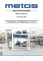
METOS Ardox IEC
3. Functional description
3.1. General
The Ardox IEC range is an appliance with two different types of heating systems. Two cooking zones
are heated by induction power source while another two cooking zones are heated by infrared (radiant)
heating elements.
3.2. Application of the appliance
The appliance is intended for preparing various kinds of foodstuffs using cookware. The range can be
used for cooking, keeping warm, flambering, roasting etc.
3.2.1. Prohibited use
Use of the appliance for any other purposes than that of mentioned above is prohibited.
Preparing of food directly on the ceramic hob surface without cookware is prohibited
3.3. Construction and operating principle
Ceramic hob surface of Ardox IEC consists of two hob elements with induction heating source and two hob
elements with infrared heating elements. Cooking zones for each hob element are marked on glass ceram-
ic surface. Induction cooking zones are marked by squares. Infrared heating zones are marked by circles.
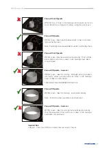
Cookware placed on ceramic hob surface within induction heating zones is heated up by means of
electromagnetic field generated by induction heating source. Electromagnetic field influences only the
bottom of cookware. Energy transfer stops immediately if cook- ware is taken away from hob surface
and starts again when cookware has been placed back on hob surface.
Cookware placed on ceramic hob surface within infrared heating zones is heated up by means of radiant
heating elements placed beneath ceramic hob surface.
3.3.1. Operating switches and indicator lights
Each cooking zone is operated by means of stepless power switch. Two power switches for induction
heating zones are located on the left side of control panel, and two power switches for infrared heating
zones are located on the right side of the control panel.
Above each power switch, there is a green LED indicator. Steady light of indicator means that power
switch is on and power is transferred to corresponding heating zone.
To generate power for infrared cooking zone, turn the corresponding switch from “0” po- sition to any
position between “1” and “6”. The maximum power is when the switch is in “6” position, and the mini-
mum when in “1” position.
To generate power for induction cooking zone, put first cookware within cooking zone and turn corre-
sponding switch from “0” position to any position between “1” and “12”. The maximum power is when
the switch is in”12” position, and the minimum power when the switch is in “1” position.
STOP
STOP