background image

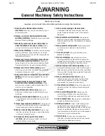
Power Operated Guillotine Safety Instructions

1.   Maintenance.


Make sure the Guillotine is turned 

off and disconnect from the main power supply 
and make sure all moving parts have come to a 
complete stop before any inspection, adjustment or 
maintenance is carried out.

2.  Guillotine Condition.


Guillotine must be 

maintained for a proper working condition. Never 
operate a Guillotine that has low oil levels, damaged 
or worn parts. Scheduled routine maintenance 
should performed on a scheduled basis.

3.  Blade Condition.


Never operate a Guillotine with a 

damaged or badly worn blades. Replace if required.

4.  Pump Direction.


Pump rotation must be in arrow 

direction otherwise the pump will be damaged.

5.  Hand Hazard.


Keep hands and fingers clear from 

moving parts. Serious injury can occur if hand or 
finger tips come between blades.

6.  Personal Protection.


Gloves are recommended 

when handling the workpieces.

7.  Authorized and trained personnel.


The machine 

must be operated by authorized and trained 
personnel. The shear is designed to be operated 
be a single user. Using the machine with more 
than one operator is forbidden, except for certain 
maintenance situations.

8.  Power outage. 

In the event of a power failure 

during use of the machine, turn off all switches 
to avoid possible sudden start up once power is 
restored.

9.  Work area hazards. 

Keep the area around the 

Guillotine clean from oil, tools, objects & chips. Pay 
attention to other persons in the area and know what 
is going on around the area to ensure unintended 
accidents.

10.   Guards. 

Operate machine only with all protective 

devices and guarding in place and operational. 
Never remove, defeat or bypass. Any presence-
sensing safeguarding used must have regular 
Safety integrity tests and records kept. These 
records must be kept for 5 years or for the life of 
the plant and be handed to any person that you 

relinquish control of the plant to. Tests include stop 
time measurements , safety distance calculations 
and inspections, with operator checks and periodic 
maintenance checks. (WHS Regulation 226) 

11.   Material. 

Material must NOT be hardened ceramic 

or glass-originated, non flat metals (at origin) e.g. 
rods, bars, tubes & pipes.

12.  Blade gap adjustment. 

Do NOT operate the 

machine without proper blade gap adjustment 
according to sheet thickness.

13.  Warning Labels. 

Take note of any warning labels 

on the machine and do not remove them. 

14.  Backgauge Area. 

Do not access the backgauge 

area, while the machine is working.

15.  Protective fence. 

Do not bridge the safety limit 

switch of the rear protective fence.

16.  Squaring arm. 

Do not use side squaring arm 

and front support arms for intermediate storage of 
workpieces.

17.   Operation. 

During the shearing process, the 

workpiece may slide or move unexpectedly. 
Therefore, the material must be handled carefully.

18.  Emergency stop. 

Use the emergency stop button 

in case of any emergency.

19.  Level machine.


Level the machine on a flat 

concrete surface by using a spirit level. 

20.  Overloading machine. 

Do not exceed the rated 

capacity of the guillotine. Please refer to the 
manual for capacities. 

21.  Hearing protection and hazards. 

Always 

wear hearing protection as noise generated from 
machine and workpiece can cause permanent 
hearing loss over time.

22.  Call for help. 

If at any time you experience 

difficulties, stop the machine and call you nearest 
branch service department for help.

Machinery House  

requires you to read this entire Manual before using this machine.

Page 35

Instructions Manual for HG-4012 (S948)

12/02/2018

Summary of Contents for HG-2504

Page 1: ...SWINGBEAM GUILLOTINE OPERATION MANUAL Edition No SB001 Date of Issue 5 07 2016 Models HG 2504 HG 2506 HG 3206 HG 3212 HG 4006 HG 4012 Page 1 Instructions Manual for HG 4012 S948 12 02 2018...

Page 2: ...SERIAL NO DATE OF MANF Note This manual is only for your reference Owing to the continuous improvement of the machine changes may be made at any time without obligation or notice Please ensure the lo...

Page 3: ...1 Preparation of the Machine 15 4 2 Omrom E3Z Safety Sensor Alignment 16 4 3 Calibrate X Axis on Controller 18 4 4 Commissioning Check List 18 5 OPERATION INSTRUCTION 5 1 Pre Operational Safety Check...

Page 4: ...ions Width mm Depth mm Height mm 3130 1530 1600 3130 1530 1600 3840 1675 1620 3925 1800 1940 4630 1800 1700 4735 2000 2040 Height of Work Table mm 740 800 800 800 800 860 Weight kgs 4000 5280 7100 110...

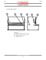
Page 5: ...2506 HG 3206 HG 3212 HG 4005 HG 4012 A 3130 3130 3840 3925 4630 4735 B 3230 3230 3990 4175 4830 4935 C 1600 1600 1620 1940 1700 2040 D 1530 1530 1675 1800 1800 2000 1 3 OVERALL DRAWINGS Page 5 Instruc...

Page 6: ...ines can be used to identify workplace hazards and to reduce the risks when using metal guillotines It is an unsafe practice for two people to work at a guillotine unless both operators are provided w...

Page 7: ...empt to cut material beyond the capacity of the machine q Never attempt to cut rod strap or wire with this machine q Use correct lifting procedures when handling large sheets of material q Take extrem...

Page 8: ...pedal control Emergency stop button engaging type is available on the foot switch control unit The foot pedal when pressed activates the shearing beam and must be held in the depressed position until...

Page 9: ...ard at the back of the machine 3 x Photoelectric safety cells are placed on both sides of the back of the machine When the beam is broken the machine stops Once the beam has been broken the system nee...

Page 10: ...n the slings are at a 45 angle then each sling will carry the equivalent of 50 of load weight Fig 2 1 When the slings are at a 90 angle then each sling will carry the equivalent of 75 of the load weig...

Page 11: ...on of the machine The sizes for the bolt holes position are listed as A B listed in the chart below Check the sizes with the distributer Model A B C D E F G HG 2504 3500 2840 1000 1750 300 130 100 HG...

Page 12: ...ocedure After your guillotine has been anchored to a concrete slab floor it then needs to be leveled The leveling is performed using the screws on each pad Fig 3 1 Loosen the hold down bolts and place...

Page 13: ...ce of the holes q Re tighten the screws Fig 3 3 3 4 ATTACHING THE ACCESSORIES q Bolt the support arms onto the feed table Ensure they are level and square to the table Fig 3 2 q Unpack and attach the...

Page 14: ...nd free from dust and dirt q Remove the oil tank cover Fig 5 5 q Using a pump add the oil into the tank q Oil level must be filled until the oil reaches the top mark of the oil indicator q Always keep...

Page 15: ...llow all setup instructions before starting hydraulic pump The safety circuit consists of a reset switch and two rear side guards each having 3 sensors Your ma chine may or may not have a RED warning...

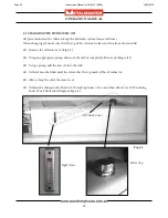
Page 16: ...he guard The receivers are wired in series so No 1 receiver will have a green light on indicating it has power When it is correctly aligned with its sender the red green light will be on and it will s...

Page 17: ...g will stop the pump and the safety circuit will have to be reset again Loosen the sender screws and angle sender up until receiver loses alignment Angle sender down until receiver re aligns and then...

Page 18: ...controller q Test cut material and check quality of cut q Tools equipment and personnel are clear of the machine q Operation Manual on how to operate the machine has been read 4 3 CALIBRATE X AXIS ON...

Page 19: ...rear of electrical box image D 6 Press OK on NC 89 control panel to activate guard system B 7 Repeat steps 1 to 6 for each sensor 2 3 A Basic Control Light on B NC 89 Control Display Emergency Stop Ch...

Page 20: ...o Count clear the number enter eg 3 and press After 3 cuts it will count down to 0 and the controller will stop cutting You must now arrow down to Count and then press for counting upwards or enter an...

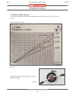
Page 21: ...Fig 5 4 to correct graduated setting Fig 5 4 5 3 SETTING THE BLADE GAP To adjust the blade gap for the material thickness and type firstly check Fig 5 3 for correct setting Adjustment Table of Gap Pa...

Page 22: ...Operator Oil leakage in cylinders Weekly Operator Hydraulic Oil Change and filter 1000hrs Maintenance Oil leakage in pipes hoses and hydraulic elements Weekly Operator Hydraulic fluid level Weekly Op...

Page 23: ...3 4 5 6 Lubricants q Cylinder and main pivot points grease q Back stop shafts screws nuts grease q Shear beam slides grease q Hydraulic oil 46 6 2 LUBRICATION POINTS Page 23 Instructions Manual for H...

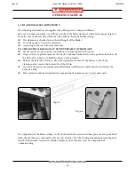
Page 24: ...oil completely Be sure nothing is left q Using a pump add the new oil into the tank q Oil level must be filled until the oil reaches the top mark of the oil indicator q Always keep the oil at the same...

Page 25: ...ace inside the oil tank q Screw the new filter into its place in the tank and replace the cover Note The suction filter element must be cleaned after the first 200 hours of use and then after every 10...

Page 26: ...to the maximum down stroke position then shut off the ball valve in Fig 6 6 to hold the down stroke position q Release the ball valve slowly to allow the upward movement of the blades to check the cl...

Page 27: ...edges 1 Check the system pressure See page 4 2 Check the oil level See page 24 3 Check the blade gap See page 21 4 Check the blade clearance See page26 5 Reset or regrind the blades as required Machin...

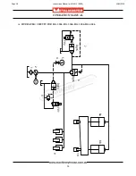
Page 28: ...28 OPERATION MANUAL A HYDRAULIC CIRCUIT FOR HG 2504 HG 2506 HG 3206 HG 4006 N D 8a 8b 10 YV1 9 3 Dg16 YV2 Dg16 5 4 2 1 3 7 6 Dg16 Page 28 Instructions Manual for HG 4012 S948 12 02 2018...

Page 29: ...29 OPERATION MANUAL A HYDRAULIC CIRCUIT FOR HG 3212 HG 4012 1 0 DG16 YA1 2 4 6 Dg25 4 YA2 Dg25 5 D N 3 1 Dg16 2 1 7 8 Page 29 Instructions Manual for HG 4012 S948 12 02 2018...

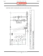
Page 30: ...30 OPERATION MANUAL B ELECTRIC CIRCUIT DIAGRAM HG 2504 HG 2506 HG 3206 HG 4006 Page 30 Instructions Manual for HG 4012 S948 12 02 2018...

Page 31: ...AM HG 2504 HG 2506 HG 3206 HG 4006 Power Switch Protection Lighting Photoelectric Switch NC89 Upper Limit Lower Limit Foot Down Oil Pump Function Transform Encoder Optional Rear Sheet Supports Page 31...

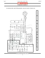
Page 32: ...32 OPERATION MANUAL B ELECTRIC CIRCUIT DIAGRAM HG 3212 HG 4012 Page 32 Instructions Manual for HG 4012 S948 12 02 2018...

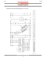
Page 33: ...33 OPERATION MANUAL B NC89 ELECTRIC CIRCUIT DIAGRAM HG 3212 HG 4012 Page 33 Instructions Manual for HG 4012 S948 12 02 2018...

Page 34: ...connecting 14 Use correct amperage extension cords Undersized extension cords overheat and lose power Replace extension cords if they become damaged 15 Keep machine well maintained Keep blades sharp a...

Page 35: ...Any presence sensing safeguarding used must have regular Safety integrity tests and records kept These records must be kept for 5 years or for the life of the plant and be handed to any person that y...

Page 36: ...ear gloves to prevent cuts from sharp material offcuts Secure support work material on table Isolate power to machine prior to any checks or maintenance Hands should be kept clear of moving parts and...

Reviews: