


5
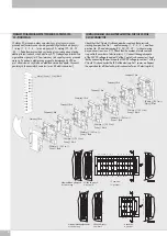
SCHEMAT POŁĄCZENIA ELEKTRYCZNEGO DLA PRZYŁĄCZA 9 –
PINOWEGO.
W złączu 9-pinowym należy sprawdzić czy piny (z czerwonymi
przewodami) umieszczone są w odpowiednich gniazdach od pozycji 1 i
rosną (1 - 2 - 3 - 4 …) oraz od pozycji 9 i maleją (9 - 8 ...). Dodatkowo
sprawdzić czy liczba pinów jest zgodna z liczbą elektro-pilotów (zobacz
widok od strony Z). Następnie potwierdzić że w gnieździe w pozycji
nr 9 umieszczony jest wspólny czarny przewód masowy. Po podaniu
elektrycznego sygnału sterującego 24VDC na pin 1 obserwować
czy dioda na elektrozaworze się zapala. Czynność powtórzyć dla
pozostałych zaworów (max. 8 elektrozaworów).
Check that the 9 pole D-sub connector has contacts that protrude starting
from position No. 1 - and increasing (1 - 2 - 3 - 4 ...), and from position
No. 9 and decreasing (9 - 8 ...) without missing any positions (see
view Z).
Check that the number of male contacts is equal to the number of
electro- 1.
Connect the negative pole of the 24VDC voltage to contact 9 of the 9
pole D-sub connector.
Check that by connecting the positive pole of 24VDC voltage to contact
1 of the 9 pole D-sub connector the LED of the electro-pilot 1 comes on.
Repeat the operation for all the electro-pilots connected (max. 8
electro-pilots).
WIRING DIAGRAM AND ELECTRICAL TESTING FOR THE 9 POLE
D-SUB CONNECTOR
8
7
1
2
3
4
5
9
8
7
6
1234
5
9
8
7
6
1234
5
Nieprawidłowe połączenie
Incorrect wiring
Widok od strony Z
View from Z
5 zaworów
5 positions
Masa (-) Czarny /
Com (-) Black
Czerwony /
Red
Czerwony /
Red
Czerwony /
Red
Czerwony /
Red
9 Masa (-) /
9 Com (-)
Czarny /
Black
9 Masa (-) /
9 Com (-)
Czarny /
Black
9 Masa (-) /
9 Com (-)
Czarny /
Black
9 Masa (-) /
9 Com (-)
Czarny /
Black


