


2
MONTAŻ I TESTOWANIE PNEUMATYCZNE
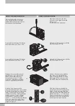
Tylne drzwiczki do zaworu otworzyć przy
użyciu wkrętaka lub palcami, zwalniając
zapadkę zabezpieczającą przed otwarciem.
Zawór ułożyć na płycie początkowej.
Open the rear door to the valve with a
screwdriver, or your fingers, to access the
blocking system.
Insert the valve on the input terminal.
ASSEMBLY AND PNEUMATIC TESTING
Za pomocą klucza imbusowego CH2 dokręcić
dolny wkręt dociskowy przy użyciu
1.5 Nm.
Tighten the rear locking grub screw with Allen
key CH2 to a torque of 1.5 Nm.
Za pomocą klucza imbusowego CH2 dokręcić
górny wkręt dociskowy przy użyciu
1.5 Nm.
Tighten the front locking grub screw with Allen
key CH2 to a torque of 1.5 Nm.
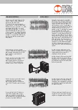
Następnie w ten sam sposób zamontować
pozostałe zawory wraz z płytą końcową.
Podczas montażu należy upewnić się,
że wypusty pozycjonujące „A” zostały
umieszczone w odpowiednich gniazdach
osadczych w poprzedzających modułach.
Continue in the same way to assemble the
other valves as far as the blind terminal.
Make sure that the small teeth “A” of each
plate engage with the successive ones and
also with the relevant seat in blind terminal.
A
A
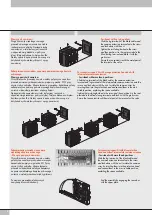
Po montażu wyspy zaworowej należy
przeprowadzić test pneumatyczny aby sprawdzić
jej szczelność. Przed podaniem ciśnienia należy
zaślepić wszystkie wyjścia zaworów (ryzyko
uszkodzenia uszczelnień w skutek gwałtownego
przepływu powietrza). Ciśnienie zasilające
należy podłączyć w oznaczone przyłącza
wtykowe 1, 11, X. Wartość ciśnienia zasilającego
musi zawsze znajdować się między dwoma
wartościami granicznymi wskazanymi przy
przyłączach wtykowych.
After fitting it is necessary to perform the
pneumatic test on the island to check general
tightness. Plug the valve output fittings and
connect the terminal input fittings marked with
identification numbers 1, 11, X to the supply.
The pressure used for the test must always be
between the two limit values indicated on the
terminal input close to each connection.


