


3
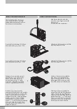
POŁĄCZENIE ELEKTRYCZNE.
Ustawić wyspę tak aby był dostęp od dołu.
Wtyczki umieścić w elektro-pilotach oraz
zagiąć przewody na zewnątrz.
W wyspach do 6 zaworów należy użyć
zestawu wtyczek 1-6 o kodzie 0226180399.
Dla liczby zaworów w wyspie od 1-12, należy
użyć wtyczek (dla modułów 1-6 wtyczek
0226180399 dla modułów 7-12 wtyczek o
kodzie 0226180400). Dla liczby zaworów
w wyspie powyżej 12-u należy użyć wtyczek
(dla modułów 1-6 wtyczek 0226180399 dla
modułów 7-12 wtyczek 0226180400 a dla
powyżej 13-go modułu wtyczek o kodzie
0226180401).
Position the island so that it is accessible
from the rear. Insert the plug-in connector kit
into the electro-pilots by bending the cables
upwards and downwards. For islands with
up to 6 positions, use the 1-6 valve plug-in
connector kit code 0226180399. For islands
with more than 6 positions and up to 12
positions, use the 1-6 valve plug-in connector
kit - code 0226180399 up to the sixth
position and then use the 7-12 valve plug-in
connector kit - code 0226180400 from the
seventh up to the twelfth position. For islands
with more than 12 positions, use the 1-6 valve
plug-in connector kit - code 0226180399 up
to the sixth position, from the seventh up to
the twelfth position use the 7-12 valve plug-in
connector kit - code 0226180400 and then
use the 13-30 valve plug-in connector kit -
code 0226180401 for the thirteenth position
onwards.
ELECTRIC WIRING
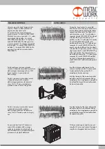
Zacisk wspólnego czarnego przewodu
umieścić w odpowiednim gnieździe przyłącza
elektrycznego oznaczonego jako pin 25/9
(masa ) zgodnie z typem przyłącza
elektrycznego.
Zaciski z czerwonymi przewodami wpinać
w odpowiednie gniazda przyłącza
elektrycznego zgodnie ze schematem ze
strony 5 lub 6. W pierwszej kolejności
przewody wpinać w dolną linię gniazd.
Insert the extension cable terminal as the
common conductor into the D-sub connector
counter-marked by the number 25/9,
according to the connector type.
Insert the terminals of the lower electro-pilot
red cables into the D-sub connector fittings
according to the wiring diagram on page 5 or
6 and lead the loops of the red cables under
the lower electro-pilots.
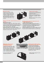
Zaciski z czerwonymi przewodami wpinać
w odpowiednie gniazda przyłącza
elektrycznego zgodnie ze schematem ze
strony 5 lub 6. Przewody wpinać w drugiej
linii.
Insert the terminals of the upper electro-pilot
red cables into the D-sub connector fittings
according to the wiring diagram on page 5 or
6 and lead the loops of the red cables under
the upper electro-pilots.
Za pomocą dwóch śrub M3 zamocować
wspornik dla przyłącza elektrycznego i
następnie za pomocą dwóch specjalnych
śrub sześciokątnych z gniazdem dla wtyczki
przymocować przyłącze elektryczne.
Fit the connector support onto the terminal
using the M3 screws and connect the support
using the two hexagonal lock screw blocks.


