


42
controlling the sensor. The regulator switches
off the fan.
16
ADDITIONAL FUNCTIONS
16.1
Power supply decay
In the cases of power supply failure, the
regulator will resume the operation mode in
which it was before the failure.
16.2
Anti-freezing protection
If the boiler temperature drops below 5
C,
the CH pump will be enabled, thus forcing
circulation of the boiler water. This will delay
the process of water freezing, yet in the case
of great frost or shortage of power, it will not
protect the system against freezing.
Note: This function must not be
the only anti-freezing protective
measure! Apply other methods
too. Regulator manufacturer is
not
liable
for
anti-freezing
related damages.
16.3
Function of protecting pumps
against stagnation
The regulator performs the function of boiler,
HUW and mixer pumps and servo protection
from locking caused by scale deposit. To do
this, these components are periodically
(every 167h) switched on for few seconds. In
this way the pumps are protected from
immobilization caused by scale deposits.
Therefore, during boiler shut-down, power
supply to the regulator should be on, and the
regulator should be in STANSTILL mode.
16.4
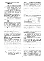
Feeder bunker
After connect an additional module B
controller can be used with the sensor low
fuel level in the tank (the fuel supply from
the bunker). Upon activation of the sensor
(opening) at the Additional feeder operation
time controller activates additional feeder in
order to supplement the base fuel tank. This
parameter can be found in:
Service settings
→
Burner settings
If the parameter Additional feeder operation
time is set to “0” this work additional feeder
is turns off.
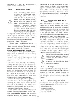
17
REPLACEMENT OF PARTS AND
COMPONENTS
17.1
Replacement of mains fuse
Mains fuse is located in the Operating Unit. It
protects the regulator and other equipment.
In case of replacement, use 6.3A.
In order to take out the fuse, raise the fuse
holder using flat-blade screwdriver and take
out the fuse.
17.2
Replacement of control panel
It is not recommended to replace only the
control panel as the software in the panel
must be compatible with the software in the
rest of the regulator
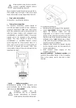
17.3
Lambda sensor
Burner efficiency can be increased by
connecting
additional
Lambda
sensor
module. Connect the module according to
electric scheme. Lambda sensor is to be
activated in:
Service settings
→
Burner settings
→
Lambda sensor
If parameter Operation with Lambda sensor
is set on ON then the controller will operate
using Lambda sensor readings. The amount
of air provided to the furnace will be
automatically set in such a way to obtain
preset amount of air in fumes. If this
parameter is set on OFF then Lambda sensor
readings will not have influence on
controller’s operation. Amounts of air for
given burner power are set in:
Boiler settings
→
Output modulation
Periodical calibration of Lambda sensor
readings can be necessary. To conduct
Lambda sensor calibration it is necessary to
extinguish the boiler. To make a successful
calibration the furnace in boiler must be
completely extinguished. To start up the
calibration use the parameter:
Boiler settings
→
Lambda calibration
Calibration process lasts approximately 8
minutes.
Summary of Contents for ecoMAX860P TOUCH
Page 2: ......
Page 6: ...6...
Page 7: ...INSTRUCTION MANUAL ecoMAX 860P TOUCH...
Page 17: ...INSTALLATION AND SERVICE SETTINGS ecoMAX 860P TOUCH...
Page 43: ......