


40
15
ALARM DESCRIPTION
15.1
Max. boiler temp. excess
Protection
against
boiler
overheating
comprises two stages. In first instance i.e.
once the Boiler cooling temp. has been
exceeded, the regulator attempts to reduce
the boiler temperature by activation of the
boiler pump, HUW pump and opening the
mixer servo (only in case mixer circuit = CH
ON). Has the temperature dropped - the
regulator returns to normal operation. Is the
temperature still increasing (and has reached
95
C), power supply to the fuel feeder and
the fan is off and permanent boiler
overheating alarm with sound signal is
produced. If, during boiler overheating time,
temperature measured by HUW sensor is
higher than Max. HUW temp., HUW pump
goes off. In this manner, users of hot utility
water are protected from burning. The alarm
is reset by switching the regulator off and on.
The alarm can be reset by restarting the
power supply.
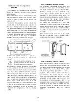
Note:
arrangement
of
temperature sensor outside the
boiler water jacket (e.g. at the
outlet pipe) is not recommended
because boiler overheating may
be detected with delay.
15.2
Exceeding max. feeder
temperature
This alarm will occur after the feeder
temperature exceeds the parameter Max.
feeder temp. If the feeder temperature
exceeds this value, the regulator will enable
the feeder for a constant, programmed time
and will activate the poker. The airflow is
disabled and the pumps are enabled. After
„pushing the fuel out”, the regulator disables
the feeder and does not activate it again,
even if the feeder temperature is still high.
This alarm can be cancelled only after the
feeder temperature decreases, by restarting
the regulator.
The function of protection against
flame recession is inoperative if the
feeder sensor is disconnected or
damaged.
The
function
of
protection against flame recession
is inoperative if the regulator is not
powered.
Regulator cannot be used as the
only protection against flame
recession in a boiler. Use
additional protective automatics.
15.3
Faulty fuel feeding system
This alarm occurs when an electronic control
circuit of the feeder is damaged. In that case
the feeder become controlled by an
electromechanical relay and because of that
feature boiler operation will not stop – which
is especially important during heating
season. The regulator then works in the safe
mode, which is indicated by a prompt
„Feeder control system failure” on the
screen.
In the event of an alarm, stop the
operation of the boiler and repair
immediately regulator.
15.4
Boiler temp. sensor damaged
This alarm occurs in case of boiler
temperature sensor damage and excess of
its measurement range. Upon occurrence of
this alarm, boiler, HUW and mixer pumps
start to possibly cool down the boiler. To
reset the alarm - switch OFF and ON the
regulator. Check the sensor and replace it, if
necessary.
Checking temperature sensors
described in this manual, in
point.12.8.
15.5
Feeder temp. sensor damaged
This alarm occurs in case of damage of fuel
feeder temperature sensor and excess of its
measurement range. To reset the alarm -
switch OFF and ON the regulator. Check the
sensor and replace, if necessary.
Checking temperature sensors
described in this manual, in
point.12.8.
15.6
Exhaust sensor temp. damaged
This alarm occurs in case of damage of
exhaust temperature sensor and excess of its
Summary of Contents for ecoMAX860P TOUCH
Page 2: ......
Page 6: ...6...
Page 7: ...INSTRUCTION MANUAL ecoMAX 860P TOUCH...
Page 17: ...INSTALLATION AND SERVICE SETTINGS ecoMAX 860P TOUCH...
Page 43: ......