6 - ORDINARY MAINTENANCE
6 - 10
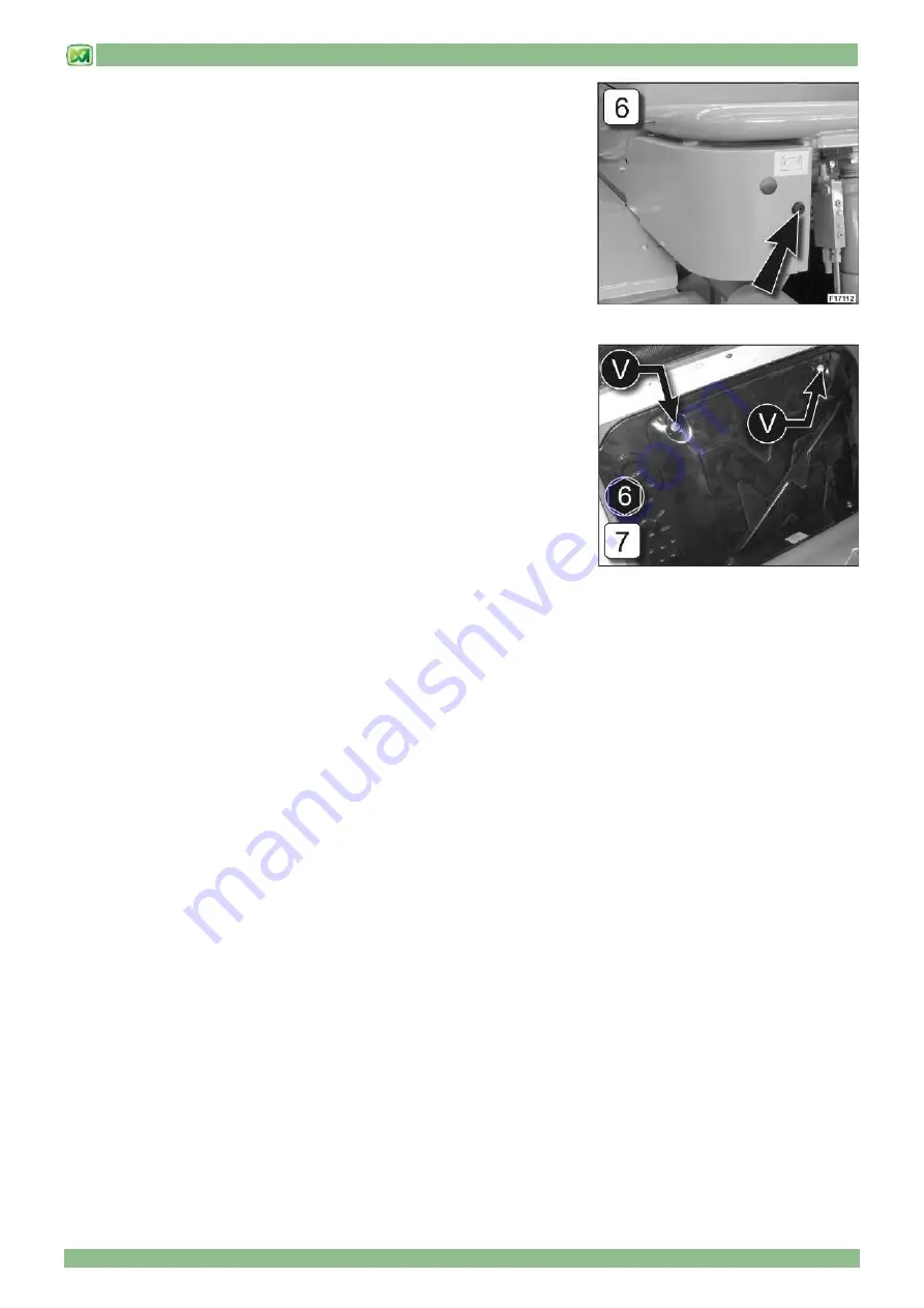
- COVER 6
COVER 6 is located in front of the cab and houses the machine electronic control
unit. Proceed as follows to remove COVER 6:
- open the lock using the specific key provided
- slide protective cover in the direction shown by the arrow
To re-close the cover, proceed as follows:
- fit the cover in its seat
- push the cover fully into place
- close the lock using the special key provided
- COVER 7
The electrical box containing the fuses, the relays and the electronic boards of
the machine can be found under COVER 7, which is located behind the driver's
seat.
Proceed as follows to open COVER 7:
• unscrew fixing screws "V"
• remove COVER 7
Proceed as follows to close COVER 7:
• rest COVER 7 on the two lower supports of the electrical box
• tighten fixing screws "V"
Summary of Contents for PANORAMIC
Page 20: ...2 MACHINE TECHNICAL INFORMATION 2 9 only for models P60 10EE P72 10EE...
Page 27: ...2 MACHINE TECHNICAL INFORMATION 2 16 DIMENSIONS P37 12 PLUS DIMENSIONS P38 12 PLUS P38 12...
Page 30: ...2 MACHINE TECHNICAL INFORMATION 2 19 DIMENSIONS P60 10 P60 10EE DIMENSIONS P72 10 P72 10EE...
Page 35: ...2 MACHINE TECHNICAL INFORMATION 2 24 LIFTING A LOAD...
Page 44: ...3 STICKERS WITH CONTROL DESCRIPTIONS LEAFLETS IN THE CAB 3 3 only for models P60 10EE P72 10EE...
Page 49: ...3 STICKERS WITH CONTROL DESCRIPTIONS LEAFLETS IN THE CAB 3 8...
Page 51: ...3 STICKERS WITH CONTROL DESCRIPTIONS LEAFLETS IN THE CAB 3 10...
Page 52: ...3 STICKERS WITH CONTROL DESCRIPTIONS LEAFLETS IN THE CAB 3 11 P37 12 PLUS P40 9 PLUS...
Page 53: ...3 STICKERS WITH CONTROL DESCRIPTIONS LEAFLETS IN THE CAB 3 12...
Page 54: ...3 STICKERS WITH CONTROL DESCRIPTIONS LEAFLETS IN THE CAB 3 13 P60 10 P72 10 P60 10EE P72 10EE...
Page 55: ...3 STICKERS WITH CONTROL DESCRIPTIONS LEAFLETS IN THE CAB 3 14 END OF SECTION...
Page 138: ......
Page 185: ......
Page 197: ...10 ELECTRICAL SYSTEM 10 1 CONTENTS GENERAL FEATURES 2 BATTERY 2 FUSES 3 END OF SECTION 4...


