G715
D
May 05
8
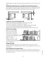
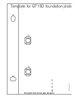
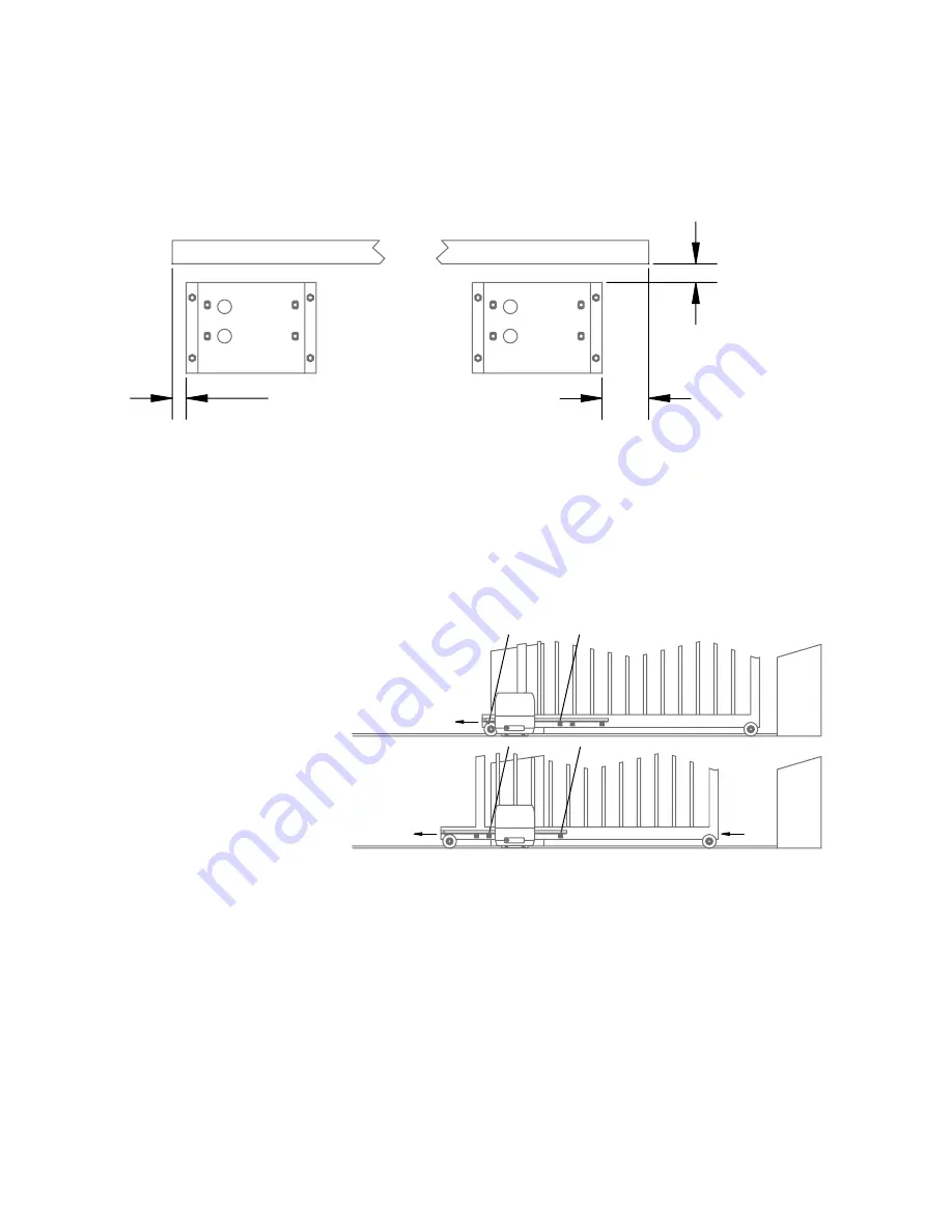
exactly parallel to the gate. The edge of the plate should be 40 mm from the face of the
gate.
Position the foundation plate correct distance from the ends of the gate
The foundation plate must be positioned to allow the gate to move fully past the opening.
If the supplied limit actuating plates are attached to the rack with no modification then the
gate must extend past the foundation plate as per the measurements shown.
Position the drive on the foundation plate
Remove the cover from the drive and place it on the foundation plate.
Centre the mounting bolts in the drive’s mounting slots.
Fit 2-mm thick spacer shims under the drive – these will be removed aftereards.
Tighten the four bolts ensuring that the drive is parallel to the gate
Operate the manual release clutch, using the key provided, pulling the lever fully out.
Fix the rack to the gate
With the clutch released,
slide the rack over the pinion
gear. Attach one end of the
rack to the gate, then slide
the gate along, attaching
each point of the rack as it
passes the pinion.
Ensure
sufficient
rack
protrudes past the sprocket
so that the limit actuators are
able to be attached.
Remove the shims
Loosen the bolts holding the drive on the foundation plate; remove the 2-mm shims.
Retighten the four mounting bolts. This provides the correct engagement of the rack and
pinion teeth.
Fit and adjust the limit actuator plates
Allow the gate to slide manually to each end position and fit the limit actuator plates to
the rack, such that the limit switch is activated. This can be fine tuned after the power is
connected to the drive.
gate
gate
40
100 min
30 min
1
2
3
4
Summary of Contents for G715D
Page 13: ...13...
Page 16: ...G715D May 05 16...


