9
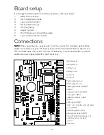
Board setup
It is strongly recommended to follow the procedures in the order below:
1.
Make all Connections
2.
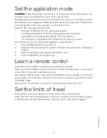
Set the application mode
3.
Learn a remote control
4.
Set the limits of travel
5.
Run Easy Setup
6.
Adjust Controls
7.
Run Professional or Easy Setup again
8.
Learn wireless remote controls
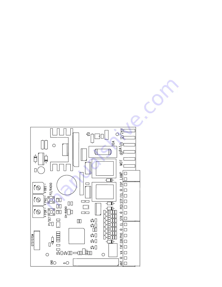
Connections
NOTE
When powering any accessories from the board, (for example: gate latches,
additional receivers, keypads, PE beams) ensure the total combined load on the VA and
TXF terminals does not exceed 150 mA. If necessary, remove accessories or provide
additional power supplies directly to each accessory.
transformer in
transformer in
battery in -ve
battery in +ve
motor out
motor out
flashing light out +ve
flashing light out -ve
opening limit switch in (NO)
ground
closing limit switch in (NO)
stop signal in (NC)
pedestrian access in (NO)
ground
start signal in (NO)
lamp / lock module signal out (grey)
ground (black)
photocell signal in (NC )
edge sensor signal in (NO)
transmitting photocell power out
accessory power out (red)
ground
antenna in
Summary of Contents for G715D
Page 13: ...13...
Page 16: ...G715D May 05 16...


