Mercury MerCruiser Series Manual Download Page 74

NOTICE

Failure to close the seawater inlet or seacock when removing or replacing the anode plugs can lead to water damage. Close

the seacock or remove and plug the seawater inlet hose to prevent water from entering the anode plug holes.

2. Close the seacock.
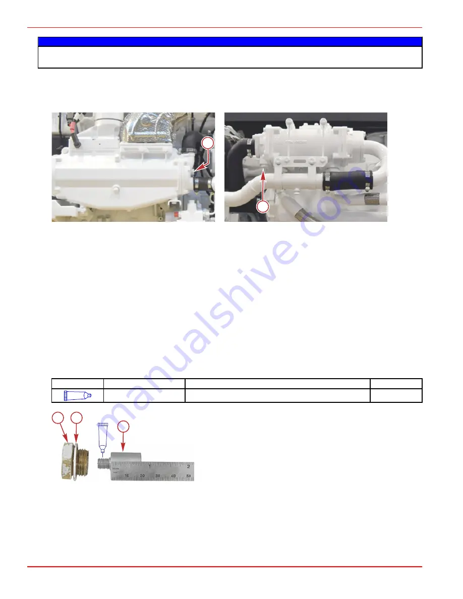
3. Remove the two anodes; one from the seawater/air heat exchanger on the port side of the engine, and one from the oil/

seawater heat exchanger on the starboard side of the engine.

NOTE: Removing the anodes will allow water to drain into the boat. Use a suitable container to catch the water.

a -

Seawater/air heat exchanger anode

b -

Oil/seawater heat exchanger anode

Cleaning and Inspection

The inspection and replacement interval will vary depending on the condition of the seawater and the mode of engine

operation.

NOTE: Use sandpaper, a fiber brush, or a cleaning pad to remove the deposits from the surface of each anode before trying to

determine the amount of erosion. Do not use a mild steel brush, which might leave deposits that could accelerate corrosion.

1. Remove the deposits from each anode.
2. Inspect and measure the anodes. Replace the anode if the length is less than 9.5 mm (0.38 in.) or if the nominal diameter

of 14.3 mm (0.56 in.) has been significantly eroded.

a. If replacement is required, remove the zinc anode from the anode hex plug by turning counterclockwise.
b. Apply Loctite 242 Threadlocker to the threads of the new zinc anode and screw it into the anode hex plug until fully

seated.

Tube Ref No.

Description

Where Used

Part No.

66

Loctite 242 Threadlocker

Zinc anode threads

92-809821

New anode shown

a -

Anode plug

b -

Sealing washer

c -

Zinc anode

Anode Installation

1. Inspect each anode sealing washer for damage. Replace as necessary.
2. Install a sealing washer onto each anode and install an anode assembly into the seawater/air heat exchanger, and into the

oil/seawater heat exchanger. Tighten the anodes to the specified torque.

65062

a

b

66048

a

b

c

Section 5 - Maintenance 

Page  68

90-8M0117076   

eng

  FEBRUARY 2018

Summary of Contents for MerCruiser Series

Page 1: ...eration are major accident prevention measures WARNING Indicates a hazardous situation which if not avoided could result in death or serious injury CAUTION Indicates a hazardous situation which if not...

Page 2: ...th Waves Logo K planes Mariner MerCathode MerCruiser Mercury Mercury with Waves Logo Mercury Marine Mercury Precision Parts Mercury Propellers Mercury Racing MotorGuide OptiMax Quicksilver SeaCore Sky...

Page 3: ...nction Display 11 SmartCraft Digital Instruments 11 System Link Digital Instruments 12 Remote Controls 12 DTS Slim Binnacle Single Handle Console Features and Operation 12 Special Digital Throttle and...

Page 4: ...lter 49 Engine Coolant 50 Checking the Engine Coolant Level 50 Inspect the Coolant Recovery Reservoir Fluid Level 51 Filling 51 Changing the Engine Coolant 51 Air Filter 53 Oil Vapor Filter 55 Fuel Fi...

Page 5: ...Away From Home 86 Stolen Power Package 86 Attention Required After Submersion 86 Replacement Service Parts 86 Parts and Accessories Inquiries 86 Resolving a Problem 86 Contact Information for Mercury...

Page 6: ...Page iv 90 8M0117076 eng FEBRUARY 2018...

Page 7: ...tput Rating 3 Conditions That Must Be Met in Order to Obtain Warranty Coverage 3 Purchaser s Responsibility 3 What Mercury Will Do 3 How to Obtain Warranty Coverage 3 Termination of Coverage 4 What is...

Page 8: ...r to Mercury Marine s warranty registration department In the United States and Canada mail to Mercury Marine Attn Warranty Registration Department P O Box 1939 Fond du Lac WI 54936 1939 920 929 5054...

Page 9: ...ion of Mercury Marine Purchaser s Responsibility Perform all regular maintenance in compliance with the schedule in the applicable Operation and Maintenance Manual Maintain records of service and main...

Page 10: ...techniques are set forth in the installation instructions for the Product Improper service Use of an accessory or part that was not manufactured or sold by Mercury Marine Operation with oils or lubric...

Page 11: ...mented Routine maintenance must be performed according to the schedule in the Operation and Maintenance manual in order to obtain warranty coverage Mercury Marine reserves the right to make any warran...

Page 12: ...or part that was not manufactured or sold by Mercury Marine Operation with oils or lubricants that are not suitable for use with the Product Alteration or removal of parts Insufficient cooling water...

Page 13: ...ment 14 Special Digital Throttle and Shift DTS Features Dual Handle ERC 15 Dock 15 Throttle Only 16 1 Lever 16 Sync 17 Transfer Boats equipped with dual helms 17 Dual Handle Yacht Console Control Oper...

Page 14: ...ls or the engine component they are secured to before sale If modifications are necessary or the emission control information label or the engine data label are damaged contact Mercury Marine about th...

Page 15: ...eeds in shallow or obstacle infested waters Releasing your grip on the steering wheel Carelessness caused by consuming alcohol or drugs High speed boating maneuvers The lanyard is a cord usually betwe...

Page 16: ...in an emergency situation such as a person overboard or a tangled propeller When activated an E stop switch interrupts the power supply to the engine and transmission If the boat is equipped with an...

Page 17: ...e VesselView operator s manual for more information 65075 VesselView 703 SmartCraft Digital Instruments The SmartCraft instrument package augments the VesselView display The instrument package may inc...

Page 18: ...tal throttle and shift DTS system required to operate this engine package provides start and stop functions throttle control shift control start in gear protection and emergency lanyard stop functions...

Page 19: ...Slim binnacle ERC Item Control Function a Stop Start Allows the operator to start or stop the engine without the use of the key switch The key switch must be in the run position for the start stop sw...

Page 20: ...a Forward b Neutral c Reverse To help prevent unwanted motion the amount of force needed to move the levers is adjustable Adjustment NOTE The control handle tension and detent tension may require per...

Page 21: ...l control lever throttle demand d Increases brightness settings for the CAN pad VesselView and SmartCraft gauges e Throttle only Allows the boat operator to increase engine RPM for warm up without shi...

Page 22: ...ttle only mode You must place the ERC levers into the neutral position to disengage throttle only mode To disengage throttle only mode 1 Place both ERC levers into neutral Throttle only will not disen...

Page 23: ...ttle and when the engines are not synchronized The light turns red when the engines are synchronized 51857 SYNC button The RPM display of VesselView also shows an orange icon under the RPM numbers if...

Page 24: ...water Turn the screw clockwise to increase tension and counterclockwise to decrease tension Adjust to tension desired 2 Detent tension adjustment screw This screw can be adjusted to increase or decre...

Page 25: ...out shifting the transmission into gear 1 LEVER Enables the throttle and shift functions of both engines to be controlled by the starboard lever SYNC Turns the auto synchronization feature off or on R...

Page 26: ...0 This allows better control of engine power in close quarter situations 31464 Dock button and light To engage dock mode 1 Place both ERC levers in neutral 2 Press the dock button located on the DTS t...

Page 27: ...ess THROTTLE ONLY The throttle only light turns off Notice that the neutral lights remain on Single Lever Mode DTS features the ability to command all engines with a single lever This feature simplifi...

Page 28: ...helm is in control of the vessel Before a transfer can be initiated the ERC levers at the active helm and at the helm intended for the transfer must be in the neutral position NOTE If you attempt to t...

Page 29: ...ders from the electrical plate assembly a Fuse box cover b 25 amp electronic diesel control EDC power c 15 amp for optional fuel priming pump d 5 amp key switch e 5 amp wake to key 12 pin f 5 amp diag...

Page 30: ...rotect the engine from damage Most faults cause the warning horn circuit to activate How the warning horn activates depends on the severity of the problem There are two warning horn states Caution Cri...

Page 31: ...oolant level Seawater pressure sensor ECM malfunction Crankshaft speed sensor Camshaft sensor Boost pressure Fuel pressure Air temperature Oil temperature Fuel temperature Exhaust gas temperature IMPO...

Page 32: ...Section 2 Getting to Know Your Power Package Notes Page 26 90 8M0117076 eng FEBRUARY 2018...

Page 33: ...ting the Engine 32 Starting a Cold Engine 32 Engine Warm Up 33 Shifting 33 Engine Shut Down Stopping 33 Protecting People in the Water 33 While You Are Cruising 33 While Boat Is Stationary 34 High Spe...

Page 34: ...of the boat Shifting the drive unit into neutral is not sufficient Use personal flotation devices Federal law requires that there be a U S Coast Guard approved life jacket personal flotation device co...

Page 35: ...oxide Poisoning Carbon monoxide CO is a deadly gas that is present in the exhaust fumes of all internal combustion engines including the engines that propel boats and the generators that power boat ac...

Page 36: ...gle of the bow too high b Operating the boat with no forward hatches open station wagon effect Important Operation Information Launching IMPORTANT Install the bilge drain plug before launching the boa...

Page 37: ...at is not fitted with a seacock leave the water inlet hose disconnected and plugged NOTE As a precautionary measure attach a tag to the key switch or steering wheel of the boat reminding the operator...

Page 38: ...en the engine hatch to air out the bilge before attempting to start the engine 2 Place the control handle in neutral 3 Turn the ignition key to the on position a Preheat is activated at key on when th...

Page 39: ...e oil filter oil lines oil line connectors and oil pan d Check for coolant leaks Check the coolant hoses and connection pipes of the heat exchanger fluid coolers aftercooler water pump and drain fitti...

Page 40: ...of the jump In such cases the landing may cause the boat to violently veer in a new direction Such a sharp change in direction or turn can cause occupants to be thrown out of their seats or out of th...

Page 41: ...speed and engine RPM Causes bow to bounce in choppy water Increases danger of following wave splashing into the boat when coming off plane At extremes can cause the boat to porpoise Shifting weight t...

Page 42: ...s 3 Operating with increased load additional passengers accessories etc Because of the many variables of boat design only testing will determine the best propeller for a particular application Refer t...

Page 43: ...d Weather 38 Antifreeze Coolant 38 Engine Oil 39 Engine Specifications 40 Fluid Specifications 40 6 7L Diesel Engine 40 Approved Paints 40 ZF Marine Transmissions 40 ZF 85 IV 41 ZF 280 IV 42 ZF 280 1...

Page 44: ...ll up you possibly received substandard fuel with a low cetane rating On engines that use high sulphur content diesel fuel this will greatly increase Corrosion on metal parts Deterioration of elastome...

Page 45: ...ntaining special additives and deionized or purified water Using other types of engine coolant may cause fouling of the heat exchangers and overheating of the engine Do not combine different types of...

Page 46: ...ling systems heat exchanger and fluid lines Always use the dipstick to determine the exact quantity of oil or fluid required All models Capacity Fluid Type Part Number Engine oil with filter 19 L 20 1...

Page 47: ...tio Hydraulic actuated multi disc clutches Suitable for twin engine installations same ratio and torque capacity in forward or reverse 12 reverse down angle Weight with fluids 92 kg 203 lbs System oil...

Page 48: ...in engine installations same ratio and torque capacity in forward or reverse 14 reverse down angle Weight with fluids 111 kg 245 lbs System oil volume 6 L 6 3 US qt Oil type general applications 15W 4...

Page 49: ...mperatures above 80 C 176 F 40W 4 Cycle Diesel Engine Oil ZF 280 1 A 59254 ZF 280 1 A ZF 280 1 A General Description and Specifications Several ratios available Refer to the identification plate for t...

Page 50: ...Section 4 Specifications Notes Page 44 90 8M0117076 eng FEBRUARY 2018...

Page 51: ...Engine Mounted Fuel Filter 59 Engine Mounted Fuel Filter Replacement 59 Transmission Maintenance 60 Checking the Fluid Level Before Operation 60 Checking the Fluid Level When Hot 61 Transmission Oil...

Page 52: ...Do not attempt repairs unless qualified Special tools and equipment are required to perform certain repairs Failure to use the correct special tools and equipment can result in severe damage to the pr...

Page 53: ...ect the oil vapor filters Clean or replace as necessary Clean the air filter Inspect and clean the seawater section of the closed cooling system Check the closed cooling fluid level and level of prote...

Page 54: ...amount of oil during operation The amount of oil consumed depends upon engine speed Oil consumption is the highest at wide open throttle and decreases substantially as engine speed is reduced NOTICE...

Page 55: ...ten securely Changing Oil and Filter Refer to the Maintenance Schedules for the change interval NOTE Change the engine oil before placing the boat in storage IMPORTANT Change the engine oil when the e...

Page 56: ...pter 11 Lubricate the O ring on the new oil filter with engine oil Do not use grease Tube Ref No Description Where Used Part No 121 15W 40 4 Cycle Diesel Engine Oil Oil filter O ring 92 858042K01 12 I...

Page 57: ...cap and tighten securely Changing the Engine Coolant CAUTION A sudden loss of pressure can cause hot coolant to boil and discharge violently resulting in serious injury from burns Allow the engine to...

Page 58: ...ty drain pan below the engine coolant drain plug 6 Remove the drain plug and allow the fluid to drain into the drain pan 7 Remove any spilled engine coolant with a shop towel and dispose the towel acc...

Page 59: ...lace the top cover and secure with the ten screws removed in step 2 Tighten the screws to the specified torque Description Nm lb in lb ft Top cover screws 10 10 1 88 5 8 8 14 Check the coolant level i...

Page 60: ...water and allow it to air dry naturally or in the sun Do not use compressed air 8 Reoil the air filter element after cleaning Apply air filter oil included with Air Filter Cleaning Kit down each plea...

Page 61: ...cover b Screws 6 2 Remove the two oil vapor filters and inspect for deposits or damage to the filter elements Replace the oil vapor filters if necessary a Oil vapor filter housing b Oil vapor filters...

Page 62: ...way from the drain plug 2 Place a suitable container below the fuel filter assembly to collect the draining water 3 Use a 9 16 in wrench to loosen the drain plug at the bottom of the fuel filter assem...

Page 63: ...to remove it from the mounting head Verify the gasket is not adhered to the mounting head b Remove the metal bowl assembly from the bottom of the fuel filter by turning counterclockwise Retain the me...

Page 64: ...filter assembly clockwise until the gasket contacts the head Tighten the filter assembly an additional 3 4 of a turn Do not use tools when installing the new filter IMPORTANT Do not fill up the new fi...

Page 65: ...iately IMPORTANT Use a suitable container to collect fuel Clean up any spills immediately and dispose of fuel in a safe manner in accordance with all local federal and international regulations IMPORT...

Page 66: ...ied torque Description Nm lb in lb ft Vent plug 24 17 7 e Once the plug is installed press the button on the hand primer pump a few more times until it is hard to pump This will ensure air is purged f...

Page 67: ...he suction device Use a back up wrench to support the evacuation hose 5 Install the oil evacuation hose plug Use a back up wrench to support the evacuation hose when tightening the connection Descript...

Page 68: ...flushing of the seawater cooling system 1 Remove the boat from the water if possible 2 If the boat is to remain in the water close the seacock 3 Level the engine if possible to ensure complete draini...

Page 69: ...y drained install the two drain plugs and tighten to the specified torque Close the heat exchanger drain petcock Description Nm lb in lb ft Aftercooler discharge pipe seawater drain plug and oil coole...

Page 70: ...into the engine seawater cooling system 15 Stop the engine 16 Remove the temporary hose from the seawater pump 17 Install the seawater inlet hose onto the seawater pump housing and secure the hose wi...

Page 71: ...ch operation in saltwater and before storage the seawater cooling system must be flushed NOTE An engine flushing attachment accessory kit P N 8M0117941 is available to provide easy and convenient flus...

Page 72: ...r until the discharge water is clear 7 Observe the water temperature gauge to ensure that the engine is operating in the normal range 8 Stop the engine 9 Shut off the water tap 10 Remove the adapter f...

Page 73: ...mp at the interval specified in the Maintenance Schedule See your Mercury Diesel authorized repair facility Corrosion Protection General Information Whenever two or more dissimilar metals such as thos...

Page 74: ...to determine the amount of erosion Do not use a mild steel brush which might leave deposits that could accelerate corrosion 1 Remove the deposits from each anode 2 Inspect and measure the anodes Repla...

Page 75: ...rs shiny or glazed Severe condition Fabric is exposed Belt is in contact with an object Can be caused by improper belt tension or tensioner failure Replace the belt and inspect for contact with an obj...

Page 76: ...the belt immediately 40799 Uneven rib wear Belt shows damage to the side with the possibility of breaks in the tensile cord or jagged edged ribs A foreign object in the pulley can cause uneven wear an...

Page 77: ...cceptable Fraying Glazed surfaces 21062 3 Check the operation of the automatic tensioner and associated components a Use a suitable tool to rotate the automatic tensioner in the direction of the arrow...

Page 78: ...ing the belt cover and remove the belt cover a Belt cover b Belt cover nuts 2 Remove the two nuts securing the belt cover attachment bracket to the studs Remove the bracket a Belt cover attachment bra...

Page 79: ...cover nuts 5 11 97 3 10 Run the engine and check that the belt is correctly positioned Battery All lead acid batteries discharge when not in use Recharge every 30 to 45 days or when specific gravity...

Page 80: ...Section 5 Maintenance Notes Page 74 90 8M0117076 eng FEBRUARY 2018...

Page 81: ...zing Temperature Seasonal Storage and Extended Storage 76 Seasonal Storage Instructions Six Months or Less 76 Extended Storage Instructions Exceeding Six Months 77 Battery 78 Recommissioning 78 6 Sect...

Page 82: ...h the seawater cooling system after each outing NOTE An engine flushing attachment accessory kit P N 8M0117941 is available to provide easy and convenient flushing of the seawater cooling system Cold...

Page 83: ...p the engine when the propylene glycol antifreeze has been drawn into the engine 10 Install the air filter 11 Clean the outside of the engine and paint damaged areas with primer and spray paint After...

Page 84: ...glycol into the environment may be restricted by law Contain and dispose of propylene glycol in accordance with federal state and local laws and guidelines 1 On engines prepared for extended storage...

Page 85: ...ng operation 12 Supply cooling water to the water inlet openings 13 Start the engine and closely observe instrumentation Ensure that all systems are functioning correctly 14 Carefully inspect the engi...

Page 86: ...Section 6 Storage Notes Page 80 90 8M0117076 eng FEBRUARY 2018...

Page 87: ...t Crank Engine or Cranks Slow 82 Engine Will Not Start or Is Hard to Start 82 Engine Runs Rough Misses or Backfires 82 Poor Performance 82 Incorrect Engine Temperature 82 Low Engine Oil Pressure 83 Ba...

Page 88: ...r air filters Replace fuel or air filters Stale or contaminated fuel If fuel is contaminated drain tank Fill with fresh fuel Fuel line or tank vent line kinked or clogged Remove obstructions from line...

Page 89: ...eck and add oil Excessive oil in crankcase causing it to become aerated Check and remove required amount of oil Check for cause of excessive oil improper filling Diluted or improper viscosity oil Chan...

Page 90: ...Section 7 Troubleshooting Notes Page 84 90 8M0117076 eng FEBRUARY 2018...

Page 91: ...on 86 Replacement Service Parts 86 Parts and Accessories Inquiries 86 Resolving a Problem 86 Contact Information for Mercury Marine Customer Service 87 Customer Service Literature 87 English Language...

Page 92: ...n both fresh and saltwater environments These conditions require numerous special parts Exercise care when replacing marine engine parts because specifications are different from those of the standard...

Page 93: ...954 744 3500 Mercury Marine 11650 Interchange Circle North Miramar FL 33025 U S A Fax 1 954 744 3535 Japan Telephone 072 233 8888 Kisaka Co Ltd 4 130 Kannabecho Sakai shi Sakai ku 5900984 Osaka Japan...

Page 94: ...ct Mercury Marine Telephone Fax Mail 920 929 5110 USA only 920 929 4894 USA only Mercury Marine Attn Publications Department P O Box 1939 Fond du Lac WI 54936 1939 Outside the United States and Canada...

Page 95: ...Section 9 Checklists Table of Contents Predelivery Inspection Checklist 90 Customer Delivery Inspection 90 9 Section 9 Checklists 90 8M0117076 eng FEBRUARY 2018 Page 89...

Page 96: ...battery controller light is illuminated verifying it is connected to power Oil and fluid levels Apply Mercury Corrosion Guard to engine package Customer Delivery Inspection IMPORTANT This checklist is...

Page 97: ...ttery switch location fuses breakers Trailer if applicable Customer is aware of the MerCathode location and controller light function Registration Complete and submit warranty registration provide the...

Page 98: ...Section 9 Checklists Notes Page 92 90 8M0117076 eng FEBRUARY 2018...

Page 99: ...Section 10 Maintenance Log Table of Contents Scheduled Maintenance Log 94 Vessel Maintenance Notes 95 10 Section 10 Maintenance Log 90 8M0117076 eng FEBRUARY 2018 Page 93...

Page 100: ...Signature Date 300 Hours Actual Hours Service Notes Dealer Name Signature Date 400 Hours Actual Hours Service Notes Dealer Name Signature Date 500 Hours Actual Hours Service Notes Dealer Name Signatu...

Page 101: ...Record all general maintenance performed on your power package here Save all work orders and receipts Date Engine Hours Maintenance Completed Servicing Dealer Section 10 Maintenance Log 90 8M0117076 e...

Reviews: