DIAGNOSTICS
SERVICE MANUAL NUMBER 24
Page 5G-34
90-861327--1 OCTOBER 1999
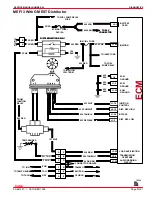
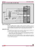
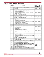
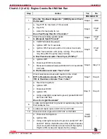
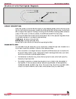
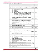
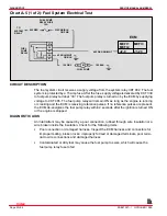
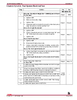
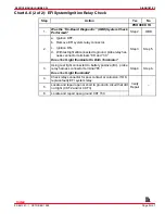
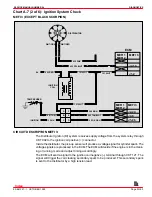
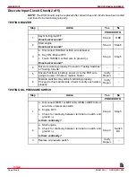
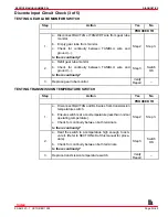
Chart A-5 (1 of 2): Fuel System Electrical Test
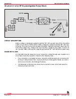
TO
SYSTEM
RELAY
FUEL PUMP
RELAY FUSE
15A
FUEL
PUMP
RELAY
A M B
FUEL PUMP
30
85
86
87
87a
902 RED
339 PNK/BLK
465 DK GRN/WHT
450 BLK/WHT
450 BLK/WHT
120 GRY
150 BLK
ECM
MEFI 1
MEFI 2
J2-9
MEFI 3
J1-23
OR PNK
OR BLK
CIRCUIT DESCRIPTION
The fuel system circuit receives a supply voltage from the system relay CKT 902. The fuel
system is protected by a 15 amp fuse. After the fuse, supply voltage is delivered by CKT 339
to fuel pump relay terminal “30.” The fuel pump relay is turned on by the ECM by supplying
voltage to CKT 465. The fuel pump relay will remain ON as long as the engine is running
or cranking and the ECM is receiving reference pulses. If no reference pulses are present,
the ECM de-energizes the fuel pump relay within 2 seconds after the ignition is turned ON
or the engine is stopped.
DIAGNOSTIC AIDS
An intermittent may be caused by a poor connection, rubbed through wire insulation or a
wire broken inside the insulation. Check for the following items:
•
Poor connection or damaged harness. Inspect the ECM harness and connectors for
improper mating, broken locks, improperly formed or damaged terminals, poor termi-
nal to wire connections and damaged harness.
•
Contaminated or dirty fuel may cause the fuel pump to seize, which will cause the
fuel pump relay fuse to fail.
Index


