FUEL INJECTION DISASSEMBLY AND REASSSEMBLY
SERVICE MANUAL NUMBER 24
Page 5E-64
90-861327--1 OCTOBER 1999
Throttle Position (TP) Sensor
NOTICE
Refer to “Service Precautions,” at front of this section BEFORE proceeding.
REMOVAL
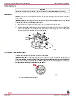
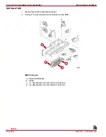
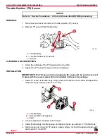
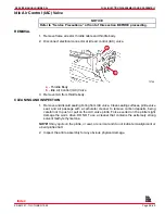
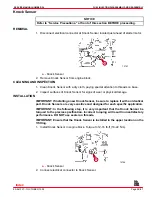
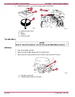
1. Disconnect electrical connector at throttle position (TP) sensor.
2. Remove TP sensor from throttle body.
73758
a
b
c
a -
Throttle Body
b -
Throttle Position (TP) Sensor
c -
Screws
CLEANING AND INSPECTION
1. Clean the surfaces of the TP sensor with a dry cloth.
2. Inspect the TP sensor for signs of wear or damage.
INSTALLATION
IMPORTANT: If the TP sensor is to be replaced with a new unit, be sure to secure it
in place with the new screws which are included in the service package.
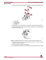
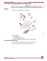
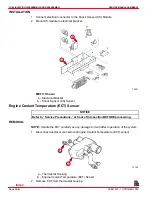
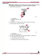
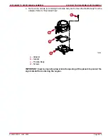
1. Install TP sensor to throttle body using screws with washers and Loctite 242 applied to
threads. Torque screws to 20 lb-in. (2 Nm).
73758
b
a
c
b
a -
Throttle Body
b -
Screws With Lockwashers
c -
Seal
2. Connect electrical connector to TP sensor.
3. Install throttle body, throttle linkage and flame arrestor as outlined in “Throttle Body.”
4. Start engine and check for TP sensor output voltage. It should be approximately .7 V
at idle and 4.5 V at WOT.
Index

