


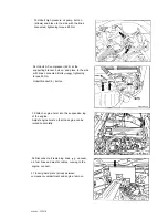


11 Disconnect engine wiring harness at the
individual connections and place over the
component compartment wall.
X 2 4
Engine
harness, shown on Model 201
Volume air flow sensor
Indicator
coolant temperature sensor (CFI),
Intake air temperature sensor, CFI
system
control module
R17
Reference resistor, CFI
system
Deceleration shutoff
ground (electric lead bolted on)
x11
block terminal TD
X24
Connector, headlamp
harness
X56
Throttle body
connector
actuator
Y6
Idle
control valve
Start valve
12 Detach twin connector (B1112) for engine
coolant temperature sensor (CFI), plug in.
Unbolt engine ground
bolt on.
Unplug throttle body switch connector (X56),
plug in.
Unplug volume air flow sensor position indicator
plug in.
01 0904
Summary of Contents for 201.024
Page 1: ...Mercedes Benz Mercedes Benz of North America Inc Montvale NJ 07645 ...
Page 5: ...General technical data 00 ...
Page 12: ...Crankcase and cylinder head 01 ...
Page 98: ...01 418 Facing cylinder head mating face POI oooe 54 Data mating face 01 0904 418il ...
Page 104: ...Crankshaft assembly 03 ...
Page 184: ...ngine timing valvetrain 05 ...
Page 243: ......
Page 255: ...I Intake I Exhaust I Data PO6 0064 N Exhaust 05 0906 29013 ...
Page 261: ...5 Insert valves and measure distance A 05 0906 291i5 ...
Page 262: ......
Page 280: ......


