background image

6


For Build 050109 and later


Making Connections 

1.


Locate  each  Flanger4Plus  unit  in  an  area  where  AC  power, 
Ethernet  connection  to  the  external  dedicated  wide  area  network 
(WAN),  and  the  local  equipment  DS1  connections  are  all 
available. 

2.


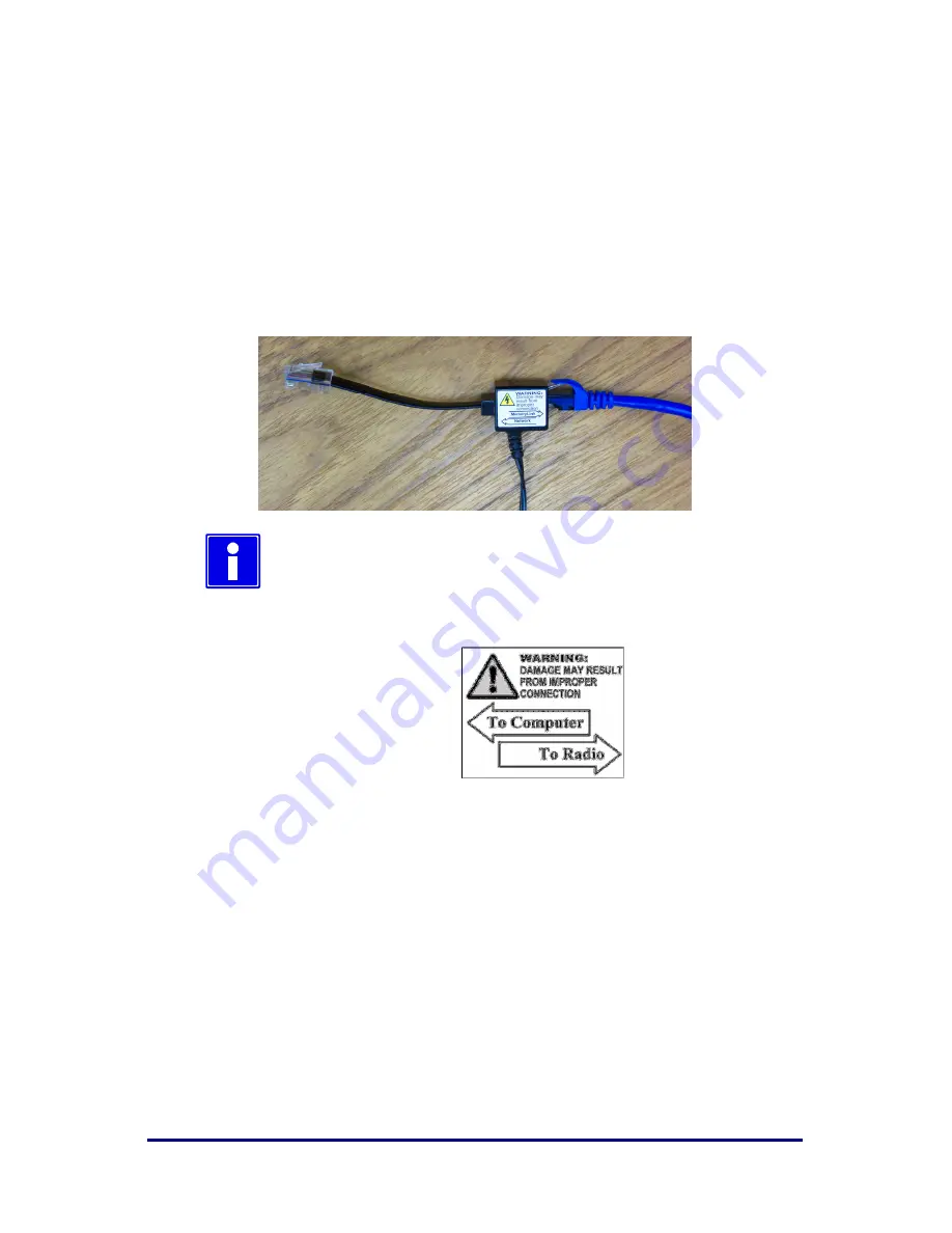
Use a CAT5 ethernet cable (blue shown) and connect the external 
power  supply  to  each  Flanger4Plus  unit’s  Local  port.  Plug  in  the 
Flanger4Plus power supply to an AC power outlet. The front panel 
status indicator will light as described on the previous page. 


The power supply’s male CAT5 connector DOES NOT 
have Power  over CAT5 and can be connected  directly 
to a PC for configuration of the Flanger4Plus. 


Label detail of power supply's power injector 


3.


(Optional) Connect the Flanger4Plus to your company’s LAN or to 
a  local  PC  via  the  male  Ethernet  cable.  The  Local  Port  Link 
indicator will light when there is active Ethernet signaling. 

4.


Connect the WAN Ethernet network via a CAT5 Ethernet cable to 
each  Flanger4Plus  unit’s  WAN  port.  The  WAN  LINK  indicator 
will light when there is active Ethernet signaling. 

Summary of Contents for Flanger 4 Plus

Page 1: ...Flanger 4 Plus Deployment Guide Part Number 9100 7000 Revision 081512 For Build 50509 and later...

Page 2: ...eps in the order given to obtain the quickest and highest quality support and service you need 1 Contact the support staff of our Partner from whom you originally bought our equipment for more informa...

Page 3: ...arrying power from the power supply to power the Flanger4Plus Observe the warning tag on the power supply when connecting Equipment connected to the WAN port WILL BE damaged if the device does not sup...

Page 4: ...follows Front Panel LED Meaning Blinking Orange WAN Link down Alternating Orange and Red Partner not found Alternating Orange and Green Loopback Restore completed Solid Green Very Good to Excellent Sy...

Page 5: ...is possible that large amounts of traffic through this port can interfere with proper operation LINK Link is present Blink indicates activity 100 Ethernet port operating speed OFF indicates 10 MB ON...

Page 6: ...t panel status indicator will light as described on the previous page The power supply s male CAT5 connector DOES NOT have Power over CAT5 and can be connected directly to a PC for configuration of th...

Page 7: ...ility Des bloque eclair sont requis pour chaque cable Ethernet qui rentre dans le local WARNING Each Lightning arrestor must have a separate and permanent connection to protective earth ATTENTION Chaq...

Page 8: ...8 For Build 050109 and later Example Interconnections Power in Flanger4Plus Power Supply LAN Flanger4Plus Power Supply P o w e r o u t P o w e r o u t LAN...

Page 9: ...factory configured and with all ports set to either Mode 2 or Mode 3 You may need to reconfigure to match your system configuration When to use Mode 2 to Mode 3 Pairs Use this configuration when conn...

Page 10: ...source and remote equipment that recovers timing from the received DS1 signal for each DS1 line independently When to use Mode 1 to Mode 3 Pairs Use this configuration when connecting network equipme...

Page 11: ...gs are used in an intra office installation For short haul T1 installations the EQ settings are directly determined by the cabling distance between the Flanger4Plus and other equipment For short haul...

Page 12: ...in the Flanger4Plus remote unit to do bench testing DS1 Crossover Cable DS1 Loop Back Plug CAT5 Ethernet Cable Diagrams Used by cable from your provider power supply into Local port and out of WAN por...

Page 13: ...Build 050109 and later 13 Accessing the User Interface In order to access the Flanger4Plus Web interface use your favorite Web Browser program e g Internet Explorer The units can be accessed as follo...

Page 14: ...nlimited and the session inactivity timeout is 600 seconds Factory Configuration Recovery In order to restore a Flanger4Plus to a factory Clock Mode 2 configuration perform the following 1 Connect the...

Page 15: ...169 254 1 50 0 0 0 0 169 254 1 60 Remote IP 169 254 1 60 169 254 1 50 Speed Duplex 100 Mbps Auto 100 Mbps Auto DS1 Defaults Unit with Clock Mode 2 Unit with Clock Mode 3 Bit Clock Source Mode 2 DS1 L...

Page 16: ...ity Console Power On and Clock Adjustment Physical 5 5 in x 7 in x 2 3 in 14 cm x 18 cm x 5 9 cm 0 8 lb 0 36 kg Power Input In line brick power supply provides 24 to 56VDC to unit requires 100 to 260...

Reviews: