background image


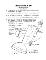
B1 Assembly 


1.


Join the FS-2 and FS-2a using a straight edge along the top of 
these parts. 

 
2.


When ready to make up the other side, assemble it right on top of 
the first side thus assuring that both sides are exactly the same. 
Use wax paper between the sides so they do not glue together. 


3.


Check to make sure both sides are exactly the same. 


4.


Glue the FS-3 to the bottom of FS-2 – FS-2a assembly. Use a 
straight edge at the bottom of FS-2a when sliding the FS-3 into 
position. Check wing saddle to be sure it matches. Again, lay the 
next side onto completed one and install FS-3. 


5.


Install the 3/4” triangle to B-1. Use a square to block B-1 to insure 
the tri-piece is flush to B-1. Draw a centerline down B-1. Now lay 
the tri-piece on B-1. It should be flush, almost back to the outward 
notches. Now the tri-piece should meet on the centerline at the 
rear. After both pieces of tri-stock are in place, you can sand or 
cut off excess tri-stock making sure it is flush with B-1. Make sure 
you don’t cut or sand off the outward notches. 


6.


Now take angle brace F-6A and at each former location, make a 
mark up the sides of the tri-stock. (The marks should slant 
towards rear B-1) Now with a knife, make a cut 1/8” wide by 1/8” 
deep at each of the marked locations. Now you should have a slot 
that each of the formers should fit in. Also at the correct angle. 


Nose Assembly 


Note: It is important that you keep F-2C very straight during assembly. 
So check F-2C throughout assembly. 
 

1.


Install the F-2 firewall to the F-2C at 90 degrees. You should 
have your centerlines drawn on the firewall. 

2.


Slide the F-2 is 90 degrees to F-2C. F-23 should also be flush 
with the back of F-2C. Make sure you sand it flush and at 90 
degrees before you install F-3. 

3.


Install F-1’s and F-3 next. Everything should be 90 degrees 
w/F-2C 

4.


Install F-1A’s 

5.


Install F-T 


Summary of Contents for 84" WING SPAN MESSERSCHMITT BF-109

Page 1: ...84 WING SPAN MESSERSCHMITT BF 109 COPYRIGHT PROTECTED 2014 ALL RIGHTS RESERVED ...

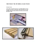
Page 2: ...ISTER 84 ME 109 SIERRA GEAR UPDATE PLEASE NOTE THE MAIN GEAR MOUNTING PLATE FROM SIERRA IS NOT SQUARE YOU HAVE TO ROUND THE INSIDE EDGE OF THE WOODEN RAILS SO THAT THEY FIT FLUSH AGAINST THE RETRACT UNIT ...

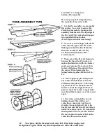
Page 3: ...ld meet on the centerline at the rear After both pieces of tri stock are in place you can sand or cut off excess tri stock making sure it is flush with B 1 Make sure you don t cut or sand off the outward notches 6 Now take angle brace F 6A and at each former location make a mark up the sides of the tri stock The marks should slant towards rear B 1 Now with a knife make a cut 1 8 wide by 1 8 deep a...

Page 4: ...d equal amounts from center of the former until proper fit acquired Once the correct fit is attained glue the former halves together Do this to F 6 F 9 10 Don t apply any glue until you are Sure of the fit of all formers Now fit all formers into place F 6 F 10 Using angle brace F 6A on the back of each former to check the angle Put F 11 in place on top of the formers Again make sure that all the f...

Page 5: ... stress for proper fit 6 The lower stringer should join into and stop at the 1 triangular stock 7 In order to properly locate the FS 1A part to the fuse side measure along the lower side stringers 24 1 8 from the front of the F 1 s 8 Install the FS 1 s with front edge on the 24 1 8 marks Install FS 1 9 You should consider installing all the control rods at this time We use the Sullivan 48 white bl...

Page 6: ...should end at F 10 Now before you add F S4A make a 1 64 or 1 32 ply doubler which goes from F 10 to the rear of FS 1B The doubler should stick up above FS B so it will be flush with the top of FS 1B when it is put in place There should be a doubler placed on both sides 15 Now you may plank the rest of the fuse at your leisure Do not plank the section on the fuse on the bottom between F 1 F 3 You s...

Page 7: ...end beyond the tip of the ribs Set aside for now 5 Place the plans on the building board Cover with wax paper Pin your bottom spar in place Place your spar brace on top of the spar Place all the ribs over their correct locations W 1 through W 12 W 1 angle should match up to the line on your spar brace This smaller version of the Meister 109 was intended to be built as a one piece wing So we are gl...

Page 8: ...and approx 1 wide Sand until flush with the ribs You will sheet over this later and drill the hole through the bottom 8 Now apply your first sheet of the top sheeting I found the best way is to do 4 sheets at a time with the first sheet starting at mid spar and working rearward Mark your spar where the sheet will start Now mark each rib on the backside of the sheet Apply CA to all areas that the s...

Page 9: ...itted on the rear doubler its sanded angled downward to it will fit under the sheeting When finished the back of the gear mechanism will be flush with the bottom of the wing sheeting Nothing should be done to the front doubler 12 The prototype ME 109 used CJM gear After the gear plate has been installed into the wing fit the retracts into place The cutout in the LG plate may have to be slightly en...

Page 10: ... open wing and aileron flap When applying the 1 8 balsa ends make sure that you sand enough off the ends so that the aileron flap will not stick out from the edge of the wing Then apply the balsa to the back of the wing and front of the aileron flaps Now slide the aileron flap back into place and sand to match the wing 18 Before you hinge the aileron flap go ahead and add the leading edge and the ...

Page 11: ...th of this piece Now cut just outside the lines and sand to fit inside the wing saddle This is the plate you will bolt the wing to On top of the plate make two x 2 x 2 doublers and glue to top of the wing bolt plate you have installed 3 Put the wing back in place Make sure you line the wing up along the centerline of the plane Now with a 13 64 drill drill through the bottom of the wing into the pl...

Page 12: ...the leading edge out of x 3 8 Then place the ribs on top and sand to a sharp edge Then you have to place the 1 8 ply hard point for the control horn The other way is to sandwich E 1 by placing the leading edge on each side Use a 3 8 x 3 8 stick for the leading edge and then ribs on each side You then need to place the tip blocks using this method ...

Page 13: ... edge INSTALLING THE TAIL TO THE FUSE 1 The fuse should be glassed tail wheel installed with your pull pull already finished for steering All your control lines should be installed for the rudder and elevators The tail should be glassed 2 You will have to take a Dremel or knife and sand cut the very rear of the triangular stock on B 1 square to accept the sq tail rudder post Now trial fit your tai...

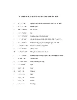
Page 14: ... F10 F10A WB Plate ETC 1 x 12 x 24 F2 Firewall gear plates Wing tongue AC PLY 1 1 32 x 12 x 12 Rear fuse doubler wing fillet 2 1 8 x 3 x 36 All fuse sides 28 3 32 x 4 x 48 Wing sheets ribs tail sheets 2 1 8 x 4 x 36 Leading edge of wing Cap for back of wing and aileron 1 tria x 36 Attach to B 1 8 3 32 x 3 x 36 Shear webbing for wing 4 3 8 x x 36 Spar 2 x x 36 Spar 16 x x 36 Stingers 3 1 8 x 3 x 36...

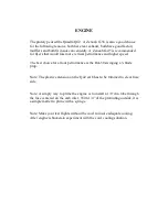
Page 15: ... The best choice for all out performance is the DA 50 swinging a 3 blade prop Note The plastic extension on the Q42 carb has to be trimmed to clear fuse side Note A simply way to prime the engine is to install a 1 8 dia tube through the fuse centered on the carb inlet With 1 4 of the protruding outside it is a simple matter to prime with a syringe Note Make your test flights without the cowl to in...

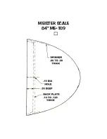
Page 16: ...MEISTER SCALE 84 ME 109 ...

Page 17: ......

Reviews: