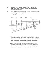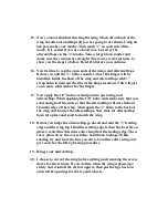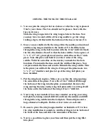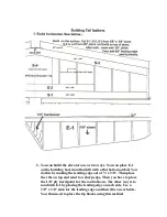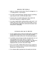
Joining the Nose Assembly and B-1
1.
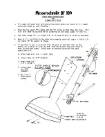
B-1 is already in place and tacked on the table. Slide the nose
assembly in place. Using clamps or rubber bands hold the nose in
place.
2.
Two bricks are handy to hold the sides against the F-3 and to hold
F-3 over the centerline.
3.
The tabs on F-3 will lock it to the holes and the sides but you
might want to block up the F-1’s to the proper level.
4.
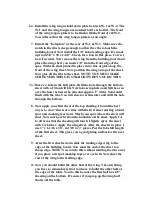
When satisfied spot glue the sides to F-1 & F-3 tabs. Install F-4 &
F-5
5.
Eyeball the top of the entire assembly for straightness. Adjust the
nose as needed. Add stringers from F-1A to F-6 and to the top of
the nose.
Note: where stringers make a sharp change in direction, cut
through and relieve the stress for proper fit.
6.
The lower stringer should join into and stop at the 1” triangular
stock.
7.
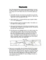
In order to properly locate the FS-1A part to the fuse side,
measure along the lower side stringers 24 1/8” from the front of
the F-1’s.
8.
Install the FS-1’s with front edge on the 24 1/8” marks. Install FS-
1.
9.
You should consider installing all the control rods at this time. We
use the Sullivan 48” white & black ones. (carbon fiber) for the
elevators. We used a pull-pull system for the rudder and tail
wheel. Don’t glue then in, place the outside rods in place until
pushed in place later on.
10.
Now install FS-1B. Once this installed, the fuse is ridged enough
to be removed from the building board.
11.
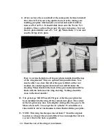
Before gluing anything to F-1’s, check to see if its parallel to the
F-2 firewall. If not, your spinner will not fit correctly. Adjust with
the braces until the balance of parts are installed.


