23
After the installation and wiring of MTC is completed, the user shall also set the parameters of MTC.
Different system configurations require different communication protocols. MTC supports two
communication protocols: Modbus and MCbus. The former as a general communication protocol, widely
support a variety of system configuration; The latter, as a communication protocol for MEGMEET, is
specially used for internal communication of MEGMEET series PLC systems. This chapter introduces
MTC communication and networking based on two communication protocols.
3.1 Modbus communication protocol
The MTC support Modbus slave station function, supports RTU and ASCII two ways, can adopt 2400,
4800, 9600, 19200 four baud rate, and can arbitrary combination frame format. Three functional codes
are supported, as shown in table 3-1. The longest frame can operate continuously with 50 BFM cells
(RTU) or 25 BFM cells (ASCII). The read and write addresses of the standard Modbus correspond to
those defined by BFM.
Table 3-1 Function code table
Function code
Description
03
Reading coil (M element)
03
Read register (BFM)
05
Write a single coil (M element)
06
Write a single register (BFM)
16
Write multiple registers (BFM)
Before power, the slave station address and working mode should be set by slave station address knob
and dial switch. The address and communication format of the slave station will not be valid until the next
time the power is switched on. The positions of MODBUS address setting knob and dial switch are shown
in figure 1-1.
Through the MODBUS address setting knob, the addresses of slave stations within 1-9 can be set.
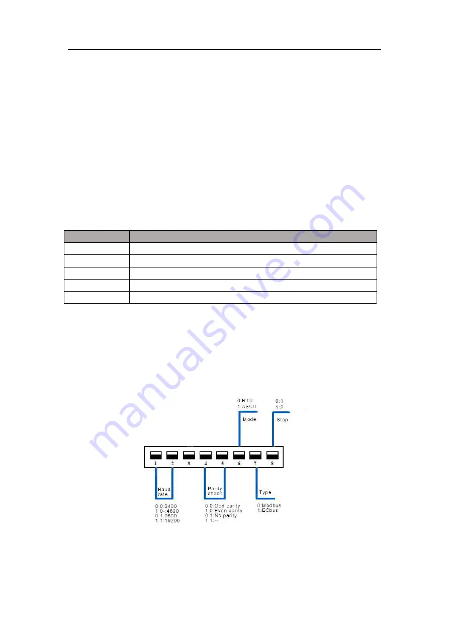
Use the dial switch to set the communication format.
The Settings of the dial switch are shown in figure 3-1.
Figure 3-1 DIP switch description
When Modicon Modbus protocol is used to read and write MTC, the logical address of Modicon Mobus
data is equal to the BFM address plus 1. For example, when the current value of the first channel is read,