Megger TM1700 Series User Manual Download Page 52

52

TM1700-sEriEs

ZP-BL16E

BL1448GE

4 CABA LOCAL 

Defining pressure transducers
1] 

Press the “Pressure” button on the “DEFINE 
NEW TRANSDUCER” screen.

Calibrating pressure transducers can be done in two 
different ways:

A] 

Manual. Enter all values (pairs of pressure & 
voltage or current value) manually.

B] 

Using the instrument readings as reference. 
Enter pressure value manually while using au-
tomatic TM 1800 voltage or current reading

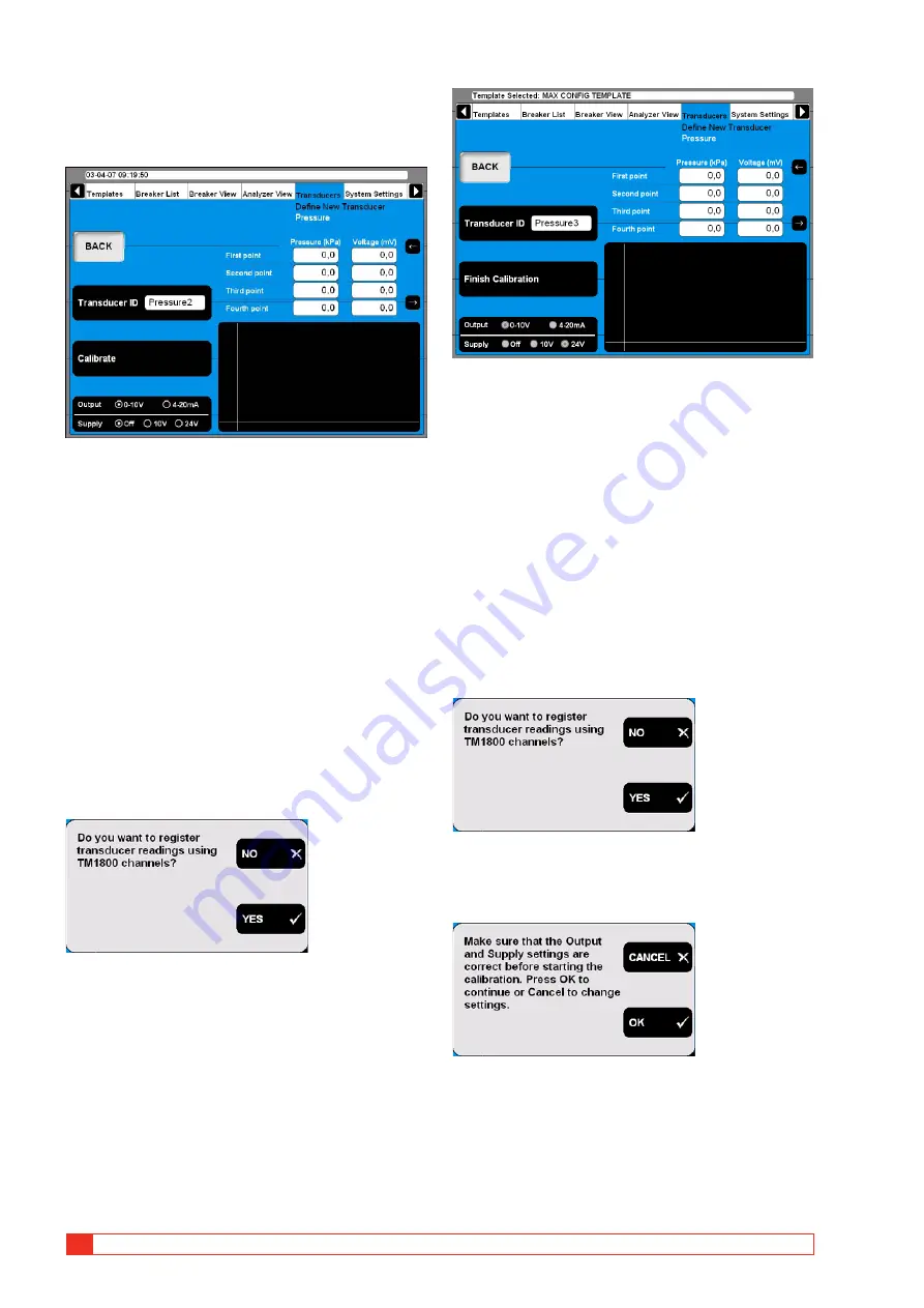
A. Manually calibrating a pressure 
transducer

1] 

Select the appropriate transducer output 
type and if needed the power supply by 
pressing the “Output/Supply” button repeat-
edly.

2] 

Press the “Calibrate” button. The following 
question appears.

3] 

Press the “NO” button. The following screen 
appears.

4] 

Enter the calibration values in the fields  
above the graphic. For quick navigation be-
tween the fields use the arrow buttons next 
to it.

5] 

Type in a significant name for the transducer 
into the “Transducer ID” field.

6] 

Press the “Finish Calibration” button.

7] 

Press the “BACK” button to leave this screen.

B. TM1700 as reference for calibrating a 
pressure transducer

1] 

Press the “Calibrate” button. The following 
question appears.

2] 

Press the “YES” button. The following screen 
appears.

3] 

Press the “CANCEL” button if those settings 
need to be corrected and start at point 1 
again. Press the “OK” button if the settings 
are correct. The following message appears.

Summary of Contents for TM1700 Series

Page 1: ...WWW MEGGER COM User s Manual Art No ZP BL16E Doc BL1448GE V06a 2017 TM1700 series Circuit Breaker Analyzer...

Page 2: ......

Page 3: ...descriptions or software listings that disclose source code are for informational purposes only Reproduction in whole or in part to create working hardware or software for other than Megger Sweden AB...

Page 4: ...____________________ 26 4 1 Start Shut down CABA Local 26 Start 26 Shut down 26 4 2 OnLine Help 27 WHAT S THIS 27 MANUAL 27 4 3 Navigation display buttons 28 4 4 Main and submenus 28 Selected items ba...

Page 5: ...m CABA Win 65 5 7 Reporting 66 Print preview 66 Send recordings to other report formats 68 5 8 Evaluate the results 69 Timing measurement 69 Motion measurement 69 Coil currents 69 Dynamic Resistance M...

Page 6: ...l Instructions All operating and us age instructions for the instrument must be followed To avoid damage do not exceed the maximum specified input limits Never do any work on a circuit breaker un less...

Page 7: ...tacts make sure the circuit breaker is closed and connected to ground on both sides The rules regarding connection to protec tive ground given above must be followed closely Neglecting these rules may...

Page 8: ...ied to your facility consult your local power company Not doing so may result in fire or electric shock or equipment damage Use an easily accessible power outlet This will ensure that you can disconne...

Page 9: ...something is burning or makes strange noise disconnect all power connec tions immediately and contact your dealer for advice 23 Replacement parts When replacement parts are required be sure the servic...

Page 10: ...ous voltages See Figure 1 3 1 Preparation of the circuit breaker Before connecting or disconnecting the instrument to a High Voltage Circuit Breaker make sure the breaker is closed and earthed grounde...

Page 11: ...th systems temporarily use a portable electrical power source use an isolating transformer the secondary side s protective earth must not be connected to the primary side s earth Remove earthing groun...

Page 12: ...igned to facilitate setup and analysis There are for ex ample integrated help functions that guides the user throughout the testing Special efforts have also been made to reduce the number of connecti...

Page 13: ...ease contact your local Meg ger representative or direct your request to the office in Sweden Contact Information Internet www megger com E mail support sweden megger com Tel 46 8 510 195 00 Fax 46 8...

Page 14: ...g If you are going to send the instrument with parcel service use the original transport box or one with equivalent strength Megger can not take responsibil ity for transport damages Note Always make...

Page 15: ...BL1448GE ZP BL16E TM1700 series 15 3 System overview...

Page 16: ...surement On top is the panel that includes all connectors for in and outputs TM1710 The TM1710 is a black box version equipped with one Control section one Timing M R section and one Digital section T...

Page 17: ...sition I indicates Closed position Note Position indicates per operating mechanism s If the Circuit Breaker has common operating mechanism only one LED will indicate the CB position SEQUENCE Indicates...

Page 18: ...shown next to it If no but tons are displayed the built in mouse is used to navigate in the menus SCREEN D C A B E A Selected items bar The arrow buttons are used to move the pointer within the appar...

Page 19: ...een O and C pulse timing may work for combined operations When there are auxiliary contacts in series the result is dependent on both con tacts and it is not possible to distinguish each contact separ...

Page 20: ...suited for 3 phase operation L1 L2 L3 RST As an option this section can be configured with three extra analog channels Cable with female XLR contact needed included in the delivery of the instrument...

Page 21: ...rmal mode 1 Keep the TUNE button pressed down for more than five seconds The DCM will confirm the mode change by flashing all LEDs simultaneously Once the TUNE button is released the tuning will start...

Page 22: ...ven tional timing i e closing time can be either graphite graphite or graphite silver transition depending on the moving contact alignment Due to this DCM and all other timing is not suitable for timi...

Page 23: ...and Print Sharing for Microsoft Networks Protocols TCP IP Protocol Settings for TCP IP Dynamic IP Address Dynamic DNS Server Address NetBIOS Enabled over TCP IP Printer Software for printers and back...

Page 24: ...ter Windows Safe Mode How to activate the SVGA output 1 Connect an external USB keyboard to the TM1700 2 Power on the TM1700 3 As soon as the first text appears on screen press the DEL button repeated...

Page 25: ...BL1448GE ZP BL16E TM1700 series 25 4 CABA Local...

Page 26: ...ton on the control panel 3 During the start up procedure the ON OFF indication lamp will blink until Windows XP starts Then all indication lamps on the con trol panel will lighten up the OPERATE and O...

Page 27: ...The keyboard button F1 does not invoke the OnLine Help function WHAT S THIS Using this option will automatically direct you to the current topic in the OnLine Help 1 Press the button WHAT S THIS 2 Mov...

Page 28: ...following instructions The arrow buttons to the left are used to move the pointer within the apparent window 4 4 Main and submenus There are six main menus 3 each having several sub menus in a tree st...

Page 29: ...few minutes 3 Wait while the instrument software files are updated 4 If asked to Close the following applications before continuing the install choose Ig nore 5 Click OK when informed Setup complet ed...

Page 30: ...ompatible Antivirus We recommend you to use Norton Antivirus software for the instrument This software is tested by Megger Sweden AB It is the user s responsibility to keep the antivirus software upda...

Page 31: ...neric template cannot be edited How to create a template 1 To create a template for a breaker you must have created the breaker in the Breaker List see 4 10 Breaker List menu on page 29 2 Create a bre...

Page 32: ...to the folder you want to rename 2 Press the CHANGE DELETE button 3 Enter the new name of the folder in the Folder ID text field 4 Press the OK button Create a template from a breaker Templates can be...

Page 33: ...n icon shows the operation level of your breaker The recording icon shows the record level of your breaker The Notebook icon shows the notebook in your breaker or test When the symbols are red crossed...

Page 34: ...e user defined drop down menu Go to the next step if you wish to add a breaker ID to the drop down menu 5 Fill in the text field with a new substation name 6 Press the Add to List button Use the De le...

Page 35: ...are done press the EXIT button Export a breaker 1 Navigate to the root level folder labeled Circuit Breaker s 2 Press the IMPORT EXPORT OF BREAKER button 3 Navigate to the breaker you want to export 4...

Page 36: ...type 6 Fill in the Type of Test text field 7 Press the Add to list button Use the De lete from list button to remove items from the list 8 Press the BACK button 9 Press the Date button if you for som...

Page 37: ...TRANSDUC ERS button 3 The Analyzer View will be shown Refer to the section 6 6 Analyzer view menu for details View a recording 1 Navigate to the measurement recording des ignation that you want to vie...

Page 38: ...t n BCCIR n Phase B close coil current circuit n CCCIR n Phase C close coil current circuit n TCIR n Common phase trip coil current circuit n ATCIR n Phase A trip coil current circuit n BTCIR n Phase...

Page 39: ...resistor contact Parameters The Parameters view shows a list of the recorded parameters List of measurement results is shown in table format Note Pass Fail limits can be also displayed here but only i...

Page 40: ...Print preview This image shows an example of a test report see 5 7 Reporting on page 38 Delete recording 1 Press DELETE RECORDING 2 Confirm delete of single recording by press ing YES Edit notes 1 Pr...

Page 41: ...Breaker set up example The setting shown above is done for a circuit breaker with three phases and a separate operating mecha nism for each phase Then it is recommended that the instrument has two Con...

Page 42: ...Press the BACK button to leave this screen Open Close 1 Use the keyboard to enter the desired value The arrow up and arrow down button can be used for quick navigation between the input fields 2 Press...

Page 43: ...tance of coil and auxiliary contacts can t be mea sured and calculated automatically Settings 1 In Breaker View Measurement Preferences press the SETTINGS button to make the settings The following scr...

Page 44: ...instrument will generate breaker control commands on the control channels If not only the measurement will take place Threshold value V Enter the appropriate value in the field if voltage mode is sele...

Page 45: ...resolution When you set the Preferred measurement time and Preferred sample interval the instrument calculates if compression is necessary If it is necessary you will get a message where you are aske...

Page 46: ...n Analyzer View you obtain information about your system configuration channel occupancy hook up instructions and so on When entering the Analyzer View the hook up screen is shown The screen shows all...

Page 47: ...press the Select button Now the transducer is selected which then is indicated by displaying the transducer name at that specific channel Monitor 1 By pressing the MONITOR button you will see informa...

Page 48: ...e position of the transducer Digital transducer outputs are pulses depending on the position of the transducer 4 20 mA transducer output is a current depending on the position of the transducer Calibr...

Page 49: ...Type in a significant name for the transducer into the Transducer ID field 5 Press the Finish Calibration button The evaluation starts and you will se the result If you get the Calibration failure mes...

Page 50: ...ame way to calibrate the remaining positions The calibration data of each position is stored automatically when moving the cursor to the next field 7 Type in a significant name for the transducer into...

Page 51: ...nsducer into the Transducer ID field 10 Press the Finish Calibration button 11 Press the BACK button to leave this screen Calibrating digital motion transducers 1 Press the Transducer type button repe...

Page 52: ...ly button repeat edly 2 Press the Calibrate button The following question appears 3 Press the NO button The following screen appears 4 Enter the calibration values in the fields above the graphic For...

Page 53: ...s the BACK button to leave this screen Defining angle transducers 1 Press the Angular button on the DEFINE NEW TRANSDUCER screen 2 Defining angle transducers is following the very same procedure as de...

Page 54: ...ORT EXPORT button the fol lowing screen appears 2 Upon pressing one of the buttons a Win dows file selection box will appear 3 Select the appropriate file and click on Open Transducers are imported fr...

Page 55: ...cer 1 Navigate to the transducer you want to delete 2 Press the Delete button 3 Confirm deletion by pressing the Yes but ton Recalibrate transducer 1 Navigate to the transducer you want to recalibrate...

Page 56: ...button repeatedly to alter the Date format Time format 1 Press the button repeatedly to alter the Time format DATE TIME 1 Press the button to set date and time as de scribed below Date time 1 Select...

Page 57: ...eport templates are grouped in three subfolders Selected Breaker s Contains all templates that come originally with the breaker e g from an imported CABA Win breaker Templates from this folder are ava...

Page 58: ...ates from the list 5 Press the Import button to import selected templates Press Exit button to abort Select printer Upon navigating to the desired printer it can be either set to be the default printe...

Page 59: ...m turning the Measure Operate knob until the operation is executed In other words the duration of the warning signal depends on the value set in the Delay of operation Sec field Stop Hardware Device 1...

Page 60: ...60 TM1700 series ZP BL16E BL1448GE 4 CABA Local Restore 1 Press the button RESTORE 2 Follow the instructions on the screen...

Page 61: ...BL1448GE ZP BL16E TM1700 series 61 5 Perform testing...

Page 62: ...tact travel shall be measured Timing and transducer cables Mounting accessories for transducers Accessories for advanced testing applications such as DRM or vibration Cables for breaker control and in...

Page 63: ...definition selected or created The instrument will choose open or close operation depending on the status of the circuit breaker The measurement will be performed according to system settings and max...

Page 64: ...tion is done only when it is required i e the first time a breaker is imported to the instrument The added parameters will initially get default values according to below After completed import the us...

Page 65: ...n Yes If applica ble i e if there is a calculated MOTION graph defined in the test plan for the corresponding Objectid Conversion Linear Conversion factor 1 Yes If applica ble i e if there is no calcu...

Page 66: ...can view and print user defined or default re ports See section 4 14 System Settings menu on page 64 Printer Report Manager Print preview Here is an example of a print out this is the parameter list I...

Page 67: ...emplates English Note If you have selected another language for CABA Local you shall enter the current lan guage e g if it is German you enter D HMI Report Templates German 7 a If you want to remove t...

Page 68: ...end recordings to other report formats Note You need Acrobat writer or similar programs to do this See section 4 7 Optional soft ware on page 65 If you have Acrobat Writer installed you can choose to...

Page 69: ...t the current at the next zero cross over It is important to interrupt the current in such a way that the arc will not re strike before the breaker contact has entered the so called damping zone Speed...

Page 70: ...aker analyzer then calculates and plots resis tance as a function of time DRM has a number of applications On circuit break ers with an arching contact design mainly SF6 types DRM can be used to measu...

Page 71: ...es 71 5 Perform testing 5 9 Store measurements Measurements are automatically stored in the instru ment To do backup Be sure you make regular backups of your record ings See Backup Restore in 4 14 Sys...

Page 72: ...se 1 Resistor contacts None Number of a contacts 1 Number of b contacts 1 Breaker View Pulse Delay Times These settings are depending on the circuit breaker type If you are uncertain please refer to t...

Page 73: ...ssary settings in Breaker View Breaker View Number of phases 3 Operating mechanism Separate Number of interrupters per phase 2 Resistor contacts None Number of a contacts 1 Number of b contacts 1 Brea...

Page 74: ...traditional internal coil current measure ment method the sum of all three close coils would be recorded The external current clamps allow the individual close coil currents to be recorded Measurement...

Page 75: ...BL1448GE ZP BL16E TM1700 series 75 7 Specifications...

Page 76: ...ware Available languages English French German Russian Span ish Swedish Translation kit available Display High brightness SVGA 800x600 Touch screen Diagonal size 21 cm 8 Keyboard On screen Control sec...

Page 77: ...range Digital section General No of channels 6 Supported types Incremental transducers RS422 Time base inaccuracy 0 01 of reading 1 sample interval Max sample rate 40 kHz Measurement time 200 s at 10...

Page 78: ...ts The position indicators on the Control Panel only show one phase The instrument sense the position of the circuit breaker via the control section i e the operating mechanism position therefore if c...

Page 79: ...t your local sales representative Can I measure the resistance of the PIR resistors Yes the PIR resistance will be measured automatically by Timing M R section if the PIR type in the circuit breaker h...

Page 80: ...unctions presented below a number of Windows functions are available moving and edit ing windows and columns and using scroll bars for example The following functions are available in the instru ment...

Page 81: ...e tailed analysis The two cursors can be moved using the mouse 1 Hold down left button pick up at left edge of window or with left right arrow keys 2 Select cursor by clicking on Time 1 or Time 2 Move...

Page 82: ...l bar in the parameter window Graph Window Labels Double clicking on any of the graph labels will open a dialogue box used for making display settings Lower Scroll bar Changes x axis offset Right Scro...

Page 83: ...isons CABA Win will give a warning when operations parameters do not match Window menu Cascade Cascade all open windows Tile Tiles all open windows on full screen Report Report a Recording This format...

Page 84: ...mplate for editing Print preview Print preview of the selected test on the selected template Generate Create a Word document Print Print the selected test on the selected template Delete Delete the se...

Page 85: ...BL1448GE ZP BL16E TM1700 series 85 10 Quick Guide...

Page 86: ...MPORTANT Always follow the safety regulations in chapter 1 of the instrument User s Manu al Always comply with local safety regula tions Note This Quick Guide instruction assumes that factory settings...

Page 87: ...er state Auto detect breaker state Note Auto detect breaker state is the default set ting in System Settings STEP 3 Inspect The measurement is performed analysed and the results will be displayed on t...

Page 88: ...rcuit breaker 64 Define new transducer 48 Defining angle transducers 53 Defining current transducers 53 Defining motion transducer 48 Defining pressure transducers 52 Defining voltage transducers 53 D...

Page 89: ...y times 41 Q Quick test 63 R Recalibrate transducer 55 Rename a subfolder 32 Rename a template 32 Repair CABA Local 29 Reporting 66 Report manager 57 Resistance measurement preferences 44 Resistive tr...

Page 90: ...for calibrating a resistive transducer 49 Top panel 19 Transducer 47 Transducers menu 48 Trig in settings 43 Troubleshooting 78 Tune the system 21 U Updating CABA Local 29 USB memory 23 User s Registr...

Page 91: ......

Page 92: ...NA FRANCE GERMANY INDIA INDONESIA JAPAN KINGDOM OF BAHRAIN KOREA MALAYSIA PAKISTAN PHILIPPINES RUSSIA SINGAPORE SOUTH AFRICA SPAIN SWEDEN SWITZERLAND TAIWAN THAILAND UNITED ARAB EMIRATES USA VIETNAM B...

Reviews: