


50
TM1700-sEriEs
ZP-BL16E
BL1448GE
4 CABA LOCAL
3]
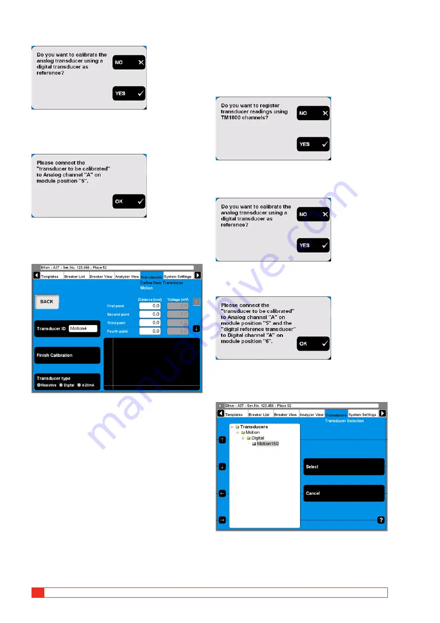
Press the “NO” button. The following mes-
sage appears.
4]
Connect the transducer to the specified chan-
nel. Confirm by pressing “OK”. The following
screen appears.
5]
Move the transducer sliding contact to the
desired position and keep it there. Enter the
“Distance (mm)” value in the field “First
point”, see screen above. The value in the
corresponding “Voltage (mV)” field will fol-
low automatically.
6]
Move the cursor to the entry field for the
second point. For quick navigation between
the fields use the arrow buttons next to it.
Proceed in the same way to calibrate the
remaining positions. The calibration data of
each position is stored automatically when
moving the cursor to the next field.
7]
Type in a significant name for the transducer
into the “Transducer ID” field.
8]
Press the “Finish Calibration” button.
9]
Press the “BACK” button to leave this screen.
C. Digital transducer as reference for
calibrating a resistive transducer
1]
Press the “Calibrate” button. The following
question appears.
2]
Press the “YES” button. The following ques-
tion appears.
3]
Press the “YES” button. The following mes-
sage appears.
4]
Connect the transducers to the specified
channels. Confirm by pressing “OK”. The fol-
lowing screen appears.
5]
Select the digital reference transducer from
the list. Press the “Select” button to contin-
ue. The following screen appears.
Summary of Contents for TM1700 Series
Page 2: ......
Page 15: ...BL1448GE ZP BL16E TM1700 series 15 3 System overview...
Page 25: ...BL1448GE ZP BL16E TM1700 series 25 4 CABA Local...
Page 61: ...BL1448GE ZP BL16E TM1700 series 61 5 Perform testing...
Page 75: ...BL1448GE ZP BL16E TM1700 series 75 7 Specifications...
Page 85: ...BL1448GE ZP BL16E TM1700 series 85 10 Quick Guide...
Page 91: ......


