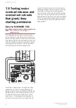


7 0
S V E R K E R 7 5 0 / 7 6 0
P r o g r a m m a E l e c t r i c A B
Z P - C D 0 1 E R 0 5 A
9.5 Measurement
section
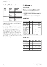
Timer
Time can be displayed in seconds or in mains-
frequency cycles.
Specifications for the time expressed in
seconds
e
g
n
a
R
n
o
i
t
u
l
o
s
e
R
y
c
a
r
u
c
c
A
s
9
9
9
.
9
-
0
0
0
s
m
1
)
%
1
0
.
0
+
s
m
1
(
±
s
9
9
.
9
9
-
0
0
.
0
1
s
m
0
1
)
%
1
0
.
0
+
s
m
0
1
(
±
s
9
.
9
9
9
9
9
-
0
.
0
0
1
s
m
0
0
1
)
%
1
0
.
0
+
s
m
0
0
1
(
±
Specifications for time expressed in mains-
frequency cycles
e
g
n
a
R
n
o
i
t
u
l
o
s
e
R
y
c
a
r
u
c
c
A
s
e
l
c
y
c
9
.
9
9
9
-
0
.
0
s
e
l
c
y
c
1
.
0
)
%
1
0
.
0
+
s
e
l
c
y
c
1
.
0
(
±
5
9
9
9
9
9
4
-
0
0
0
1
z
H
0
5
t
a
s
e
l
c
y
c
e
l
c
y
c
1
)
%
1
0
.
0
+
e
l
c
y
c
1
(
±
4
9
9
9
9
9
5
-
0
0
0
1
z
H
0
6
t
a
s
e
l
c
y
c
e
l
c
y
c
1
)
%
1
0
.
0
+
e
l
c
y
c
1
(
±
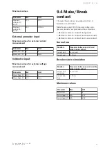
Ammeter
Switching between ranges can be carried out either
automatically or manually as desired.
The measured current can be displayed in amperes
or as a percentage of a presettable nominal value.
AC current is measured as true RMS.
DC current is measured as a mean value.
The external current measurement input is protected
by a 6 A miniature circuit breaker, and input resist-
ance Rin is 0.22
Ω
.
The values specified below are for measurement
intervals (times) longer than 100 ms. The measure-
ment error is greater for shorter measurement
intervals.
Specifications for current in amperes
-
t
s
e
T
t
n
i
o
p
e
g
n
a
R
n
o
i
t
u
l
o
s
e
R
f
o
%
(
y
c
a
r
u
c
c
A
)
A
m
+
g
n
i
d
a
e
r
A
0
1
-
0
C
A
A
2
:
C
A
A
9
9
.
1
-
0
1
.
0
C
A
A
m
0
1
)
A
m
0
1
+
%
1
(
±
C
A
A
0
2
:
C
A
A
9
9
.
9
1
-
0
0
.
2
C
A
A
m
0
1
)
A
m
0
2
+
%
1
(
±
A
0
4
-
0
C
A
A
8
:
C
A
A
9
9
.
7
-
0
4
.
0
C
A
A
m
0
1
)
A
m
0
1
+
%
1
(
±
C
A
A
0
8
:
C
A
A
9
9
.
9
7
-
0
0
.
8
C
A
A
m
0
1
)
A
m
0
8
+
%
1
(
±
A
0
0
1
-
0
C
A
A
0
2
:
C
A
A
9
9
.
9
1
-
0
0
.
1
C
A
A
m
0
1
)
A
m
0
2
+
%
1
(
±
C
A
A
0
0
2
:
C
A
A
9
9
.
9
9
-
0
0
.
0
2
C
A
A
m
0
1
:
C
A
A
9
.
9
4
2
-
0
.
0
0
1
C
A
A
m
0
0
1
)
A
m
0
0
2
+
%
1
(
±
n
r
e
t
x
E
C
A
A
6
.
0
:
C
A
A
9
9
5
.
0
-
0
0
0
.
0
C
A
A
m
1
)
A
m
2
+
%
1
(
±
C
A
A
6
:
C
A
A
9
9
9
.
5
-
0
0
6
.
0
C
A
A
m
1
)
A
m
0
2
+
%
1
(
±
C
D
A
6
.
0
:
C
D
A
9
9
5
.
0
-
0
0
0
.
0
C
D
A
m
1
)
A
m
2
+
%
5
.
0
(
±
C
D
A
6
:
C
D
A
9
9
9
.
5
-
0
0
6
.
0
C
D
A
m
1
)
A
m
0
2
+
%
5
.
0
(
±
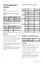
Specifications for current displayed as a
percentage of a presettable nominal value.
n
o
i
t
u
l
o
s
e
R
e
g
a
t
n
e
c
r
e
P
n
o
i
t
u
l
o
s
e
R
e
u
l
a
v
l
a
n
i
m
o
N
y
c
a
r
u
c
c
A
%
1
:
%
9
9
9
-
0
0
0
A
1
:
A
9
9
9
-
0
0
0
%
1
Voltmeter
Switching between ranges can be carried out either
automatically or manually as desired.
The measured voltage can be displayed in volts or
as a percentage of a presettable nominal value.
AC voltage is measured as a true RMS.
DC voltage is measured as a mean value.
The input is protected by a PTC resistor, and input
resistance Rin is 220 k
Ω
.
The values specified below are for measurement
intervals (times) longer than 100 ms. The measure-
ment error is greater for shorter measurement
intervals.
Summary of Contents for Programma Sverker 750
Page 1: ...SVERKER 750 760 User s manual Relay Test Unit ...
Page 28: ...2 9 S V E R K E R 7 5 0 7 6 0 P r o g r a m m a E l e c t r i c A B Z P C D 0 1 E R 0 5 A ...
Page 75: ...7 6 S V E R K E R 7 5 0 7 6 0 P r o g r a m m a E l e c t r i c A B Z P C D 0 1 E R 0 5 A ...
Page 76: ...Subject to change without notice Printed matter ZP CD01E R05B 2007 ...


