5 5
S V E R K E R 7 5 0 / 7 6 0
P r o g r a m m a E l e c t r i c A B
Z P - C D 0 1 E R 0 5 A
7.2 Testing over-
current relays
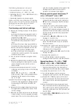
The following functions are to be tested:
• Pick-up functions: I > ON and I >> ON
• Drop-out functions: I > OFF and I >> OFF
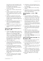
• Operating times: I > ON + TIME DELAY and I
>> ON + TIME DELAY
Test hookup and initial settings
1.
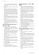
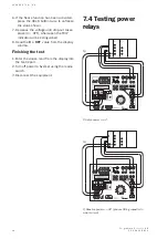
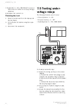
Connect for testing as shown in the above
diagram.
a.
Connect the Sverker current output to
the protective relay equipment.
b.
Connect the timer stop input (STOP) to
the relay trip output.
c.
If the test current is not too high, you
can connect one or more resistors into the
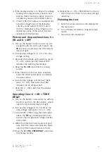
6.
Read the
U > ON + TIME DELAY
value from
the Sverker display window.
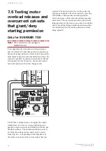
7.
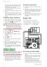
Repeat the U > ON + TIME DELAY run two
or three times to confirm its accuracy
through repetition.
8.
Decrease the voltage to 0.
Finishing the test
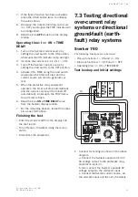
• Enter the values read from the display into
the test report.
• Turn off power to Sverker using the mains
switch.
• Disconnect the equipment.
Summary of Contents for Programma Sverker 750
Page 1: ...SVERKER 750 760 User s manual Relay Test Unit ...
Page 28: ...2 9 S V E R K E R 7 5 0 7 6 0 P r o g r a m m a E l e c t r i c A B Z P C D 0 1 E R 0 5 A ...
Page 75: ...7 6 S V E R K E R 7 5 0 7 6 0 P r o g r a m m a E l e c t r i c A B Z P C D 0 1 E R 0 5 A ...
Page 76: ...Subject to change without notice Printed matter ZP CD01E R05B 2007 ...

