1 0
S V E R K E R 7 5 0 / 7 6 0
P r o g r a m m a E l e c t r i c A B
Z P - C D 0 1 E R 0 5 A
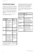
3.2 Current source
The main source built into Sverker can provide 0-
100 A, 0-40 A, 0-10 A, 0-250 V AC or 0-300 V DC,
depending on which output is used. As a rule, this
current source is used to provide simulated sudden-
change fault conditions for the object being tested.
Values are set using the main knob on the control
panel. Current, voltage and other settings appear on
the display. See section headed ”Ammeter and
voltmeter”.
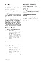
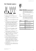
Generation is turned on and off using the start
switch which has four positions:
n
o
i
t
a
c
i
d
n
I
e
t
a
t
S
o
t
d
e
s
U
E
M
I
T
+
N
O
s
i
e
c
r
u
o
s
t
n
e
r
r
u
C
e
h
t
l
i
t
n
u
d
e
t
a
v
i
t
c
a
d
e
t
s
e
t
g
n
i
e
b
t
c
e
j
b
o
e
h
T
.
d
e
t
a
r
e
p
o
s
a
h
n
e
h
t
s
i
e
m
i
t
n
o
p
u
e
r
e
h
w
,
d
e
y
a
l
p
s
i
d
s
n
r
u
t
e
r
r
e
k
r
e
v
S
e
h
t
o
t
y
l
l
a
c
i
t
a
m
o
t
u
a
.
*
e
d
o
m
F
F
O
e
r
u
s
a
e
M
s
e
m
i
t
g
n
i
t
a
r
e
p
o
-
r
e
v
o
r
o
f
-
g
a
t
l
o
v
/
t
n
e
r
r
u
c
y
t
i
t
n
e
r
e
h
t
o
/
e
.
s
y
a
l
e
r
F
F
O
s
i
e
c
r
u
o
s
t
n
e
r
r
u
C
.
f
f
o
d
e
n
r
u
t
e
h
t
f
f
o
n
r
u
T
.
e
c
r
u
o
s
t
n
e
r
r
u
c
N
O
s
i
e
c
r
u
o
s
t
n
e
r
r
u
C
.
)
d
e
t
a
v
i
t
c
a
(
n
o
d
e
n
r
u
t
s
g
n
i
t
t
e
s
e
k
a
M
-
k
c
i
p
d
n
i
f
d
n
a
t
u
o
-
p
o
r
d
/
p
u
.
s
t
i
m
i
l
E
M
I
T
+
F
F
O
s
i
e
c
r
u
o
s
t
n
e
r
r
u
C
e
h
t
n
e
h
W
.
f
f
o
d
e
n
r
u
t
d
e
t
s
e
t
g
n
i
e
b
t
c
e
j
b
o
e
h
t
,
d
e
t
a
r
e
p
o
s
a
h
,
d
e
y
a
l
p
s
i
d
s
i
e
m
i
t
r
e
k
r
e
v
S
n
o
p
u
e
r
e
h
w
y
l
l
a
c
i
t
a
m
o
t
u
a
s
n
r
u
t
e
r
.
e
d
o
m
F
F
O
e
h
t
o
t
e
r
u
s
a
e
M
s
e
m
i
t
g
n
i
t
a
r
e
p
o
-
r
e
d
n
u
r
o
f
-
g
a
t
l
o
v
/
t
n
e
r
r
u
c
y
t
i
t
n
e
r
e
h
t
o
/
e
.
s
y
a
l
e
r
r
e
t
f
a
d
e
t
p
u
r
r
e
t
n
i
s
i
n
o
i
t
a
r
e
n
e
g
,
s
r
u
c
c
o
p
i
r
t
n
e
h
W
)
*
e
h
t
s
e
t
a
l
u
m
i
s
y
a
l
e
d
s
i
h
T
.
s
e
l
c
y
c
s
n
i
a
m
f
o
r
e
b
m
u
n
a
y
a
l
e
d
f
o
h
t
g
n
e
l
e
h
T
.
e
m
i
t
g
n
i
k
a
e
r
b
s
’
r
e
k
a
e
r
b
t
i
u
c
r
i
c
.
r
e
s
u
e
h
t
y
b
t
e
s
e
b
n
a
c
An indicator lamp to the right of the set of resistors
is lighted during generation. Generation start-up is
synchronized with the mains, thus eliminating
inaccuracies in the test results attributable to the
instant at which the start switch is activated.
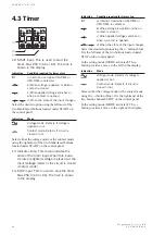
There are a number of different types of generation,
and they are selected via the display window
(Chapter 5).
n
o
i
t
a
r
e
n
e
g
f
o
e
p
y
T
n
o
i
t
a
n
a
l
p
x
E
t
a
h
t
n
o
i
t
a
r
e
n
e
G
e
h
t
l
i
t
n
u
s
e
u
n
i
t
n
o
c
d
e
t
s
e
t
g
n
i
e
b
t
c
e
j
b
o
s
p
i
r
t
e
h
t
l
i
t
n
u
s
e
u
n
i
t
n
o
c
n
o
i
t
a
r
e
n
e
G
.
s
p
o
t
s
r
e
m
i
t
y
r
a
t
n
e
m
o
M
-
e
l
l
o
r
t
n
o
c
-
y
l
l
a
u
n
a
m
(
n
o
i
t
a
r
e
n
e
g
)
d
o
t
r
e
s
u
e
h
t
s
t
i
m
r
e
p
s
i
h
T
-
y
l
l
a
u
n
a
m
,
f
e
i
r
b
e
d
i
v
o
r
p
s
i
t
a
h
t
n
o
i
t
a
r
e
n
e
g
d
e
l
l
o
r
t
n
o
c
n
e
h
w
y
l
e
t
a
i
d
e
m
m
i
d
e
t
p
u
r
r
e
t
n
i
.
d
e
s
a
e
l
e
r
s
i
h
c
t
i
w
s
t
r
a
t
s
e
h
t
d
e
t
i
m
i
l
-
e
m
i
T
n
o
i
t
a
r
e
n
e
g
m
u
m
i
x
a
m
a
t
e
s
n
a
c
u
o
y
,
e
r
e
H
t
i
n
e
h
W
.
n
o
i
t
a
r
e
n
e
g
r
o
f
e
m
i
t
s
i
n
o
i
t
a
r
e
n
e
g
,
s
e
r
i
p
x
e
.
y
l
e
t
a
i
d
e
m
m
i
d
e
t
p
u
r
r
e
t
n
i
d
e
t
r
a
t
s
e
R
o
t
d
e
s
u
(
n
o
i
t
a
r
e
n
e
g
c
i
t
a
m
o
t
u
a
t
s
e
t
)
s
e
c
i
v
e
d
g
n
i
s
o
l
c
e
r
o
s
r
e
k
r
e
v
S
e
h
t
t
e
s
n
a
c
u
o
Y
e
b
l
l
i
w
n
o
i
t
a
r
e
n
e
g
t
a
h
t
n
e
h
w
)
n
i
a
g
a
t
r
a
t
s
(
d
e
t
r
a
t
s
e
r
s
i
t
u
p
n
i
t
r
a
t
s
r
e
m
i
t
e
h
t
d
e
s
u
s
i
e
r
u
t
a
e
f
s
i
h
T
.
d
e
t
a
v
i
t
c
a
g
n
i
s
o
l
c
e
r
c
i
t
a
m
o
t
u
a
t
s
e
t
o
t
.
s
e
c
i
v
e
d
Summary of Contents for Programma Sverker 750
Page 1: ...SVERKER 750 760 User s manual Relay Test Unit ...
Page 28: ...2 9 S V E R K E R 7 5 0 7 6 0 P r o g r a m m a E l e c t r i c A B Z P C D 0 1 E R 0 5 A ...
Page 75: ...7 6 S V E R K E R 7 5 0 7 6 0 P r o g r a m m a E l e c t r i c A B Z P C D 0 1 E R 0 5 A ...
Page 76: ...Subject to change without notice Printed matter ZP CD01E R05B 2007 ...


