background image


画面調節

8

 4 接続

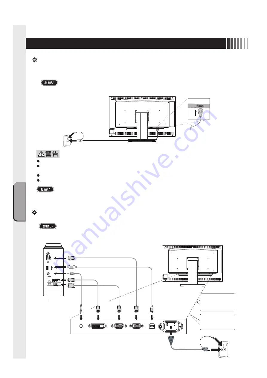
電源の接続

電源コンセントの周辺は、電源プラグの抜き差しが容易なようにしておいてください。
This socket-outlet shall be installed near the equipment and shall be easily accessible.

コンピュータに接続する前に、本機、コンピュータおよび周辺接続機器の電源を切ってください。

アースリード線を接地(アース接続)してから電源プラグをAC100V電源コンセントに接続してください。
コンピュータ本体の電源コンセントに接続するときは、電源容量を確認してください。(1.0A以上必要です。)

表示された電源電圧以外で使用しないでください。火災・感電の原因になります。
故障のとき感電の原因となりますので、電源プラグのアースリード線は必ず接地(アース)

してください。

また、

電源プラグのアースリード線は電源コンセントに挿入または接触させないでください。火災・感電の原因となります。

本機に添付している電源コードは本機専用です。安全のため他の機器には使用しないでください。
付属の電源コードはAC100V専用です。AC100V以外でご使用になる場合は、

別途電源電圧に合った電源コードをご用意ください。

ケーブルの接続

ケーブルは、接続後必ずそれぞれの固定ネジで確実に固定してください。

ケーブルを接続する前に、本機、コンピュータおよび周辺機器の電源を切ってください。

アースリード線

電源コード

シリアルポート 

DVI-D

φ3.5ステレオ

ミニジャック

コンピュータ

ミニD-Sub 15

USB

(タイプB)

D-Sub 9 

1

電源コード 

USBポート 

1:電源コード 

5:タッチ通信ケーブル(D-Sub 9) 
6:タッチ通信ケーブル(USB タイプB)

4:映像信号ケーブル(ミニD-Sub 15) 

3:映像信号ケーブル(DVI-D)  

2:オーディオケーブル(φ3.5ステレオミニジャック) 

タッチ通信ケーブルは
5または6どちらかのみ
を接続します。

映像信号ケーブルは 
3または4どちらかのみ 
を接続します。 

VGA出力 

2

VGA
入力

DVI出力 

3

DVI
入力

オーディオ出力 

4

オーディオ
入力

5

USB

USB

RS-232C

6

RS232C

Summary of Contents for TSD-ST241W-CN

Page 1: ...2 3 6 6 7 7 OSD OSD 8 8 8 9 9 10 11 17 17 19 19 20 20 21 22 12 12 13 14 15 http www mee co jp sales visual touch monitor 24 TSD ST241W CN...

Page 2: ...2 VCCI B VCCI Windows Microsoft Corporation...

Page 3: ...3 AC100V...

Page 4: ...4 During servicing disconnect the plug from the socket outlet...

Page 5: ...5 This Touch monitor is designed for use in Japan and can not be used in any other countries 40 70cm OA...

Page 6: ...6 P7 ON 1 OSD 2 3 1 3 2 OSD OSD P11...

Page 7: ...7 D Sub 15 D Sub 15 2 DVI D DVI D 2 D Sub 9 D Sub 9 CD ROM D Sub15 DVI D Kensington USB A USB B D Sub9 USB 0 OFF 1 ON...

Page 8: ...e installed near the equipment and shall be easily accessible AC100V 1 0A AC100V AC100V DVI D 3 5 D Sub 15 USB B D Sub 9 1 USB 1 5 D Sub 9 6 USB B 4 D Sub 15 3 DVI D 2 3 5 5 6 3 4 VGA 2 VGA DVI 3 DVI...

Page 9: ...9 2 30 0 80 0kHz 50 0 75 0Hz 1 1 2 OSD Auto Setup H Positiion V Position Phase Clock 3 Yes No DOS 2 1 2 OSD P11 3...

Page 10: ...10 OSD OSD OSD On Screen Display OSD OSD OSD...

Page 11: ...st Display Color Mode Clock Phase Management Exit 0 100 90 0 100 90 Display 50 50 Color Mode Cool 9300K Neutral 6500K Warm 5400K User R G B Clock Phase Management Exit Full Aspect 1 1 P13 OSD OSD H Po...

Page 12: ...19 8 800 x 600 46 88 75 00 9 848 x 480 29 83 60 02 10 848 x 480 37 57 74 84 11 1024 x 768 48 36 60 00 12 1024 x 768 56 48 70 07 13 1024 x 768 60 02 75 03 14 1152 x 864 67 50 75 00 15 1280 x 960 60 00...

Page 13: ...70 1920 1080 2 67 2 67 1920 1068 IBM VGA 800 600 2 40 1 80 1920 1080 1 80 1 80 1440 1080 SVGA 848 480 2 26 2 25 1920 1080 2 25 2 25 1908 1080 WVGA 1024 768 1 88 1 41 1920 1080 1 41 1 41 1440 1080 XGA...

Page 14: ...14 45W 2W DPMS Display Power Management Signaling OFF R G B VESA DPMS...

Page 15: ...2000 Windows XP WindowsVista Windows 7 CD ROM CD ROM Windows 2000 Windows XP WindowsVista Windows 7 CD ROM Administrator Windows 3 1 WindowsNT 4 OS 2 Macintosh CD ROM CD ROM CD ROM CD ROM index html...

Page 16: ...16 4 5 6 7 4 CD ROM USB 5...

Page 17: ...17 5 4 6 7 1 2 8 9 10 3 1 ON P6 7 2 3 1 OSD Contrast Brightness OSD P11 2 1 P14 2 3 1 1 1 2 4 1 OSD Management Scaling P13 Full 3...

Page 18: ...18 1 LED 1 1 AC100V 5 5 2 3 1 AC100V 5 5 2 3 CD ROM P16 6 7 8 9 1 2 OSD Mute OFF 10 1 1 5...

Page 19: ...19 TSD ST241W CN OFF 1 1...

Page 20: ...20 9 2 TSD ST241W CN 1 TEL 1 2 3 1 2 3 4 5 4...

Page 21: ...RS232C USB 0 7Vp p 75 RGB TMDS TTL TTL 30 0kHz 80 0kHz 50 0Hz 75 0Hz 1677 3000 1 531 36 H 298 89 V mm 270cd m2 D Sub15 DVI D D Sub9 USB type B 3 5 1W 1W 5 35 10 80 RH AC100V 240V 50 60Hz 45W UL c UL...

Page 22: ...22 2 3mm 3 2mm VESA 100mm 120 155N cm 10 12mm M4 VESA 7 5kg 4 100mm 2 3mm 3 2mm...

Page 23: ...se harmful interference to radio communications However there is no guarantee that interference will not occur in a particular installation If this equipment does cause harmful interference to radio o...

Page 24: ...40D871104C10 http www mee co jp...

Page 25: ...witch Function Power Management Function Software Installation for Touch driver 7 Trouble Shooting If the Device Malfunctions Cleaning Instructions 8 Addendum Specifications When you Install an Custom...

Page 26: ...h wire Beware of high voltage indicated on the back surface of the unit The symbols used in this User s Manual and their meanings are as following The dangers and the degree of danger possible as a re...

Page 27: ...ay cause fire or electric shock This device comes with a power cord AC100V compatible with the power outlets in general households When operating at voltages other than AC100V max AC240V be sure to us...

Page 28: ...ric shock Check that you have unplugged the power cable and disconnected the cables connecting the device to other machines before you move it Prohibited Hold the power plug firmly to unplug it Pullin...

Page 29: ...screen display with Screen Saver etc Wipe the dust etc from the power plug regularly May cause fire Clean and inspect connection of your power plug once a year Remove dust For use in Japan only This T...

Page 30: ...dial is turned 2 It turns clockwise Above of menu setting value increase 3 It turns anti clockwise Below of menu setting value decrease 1 3 2 In the operation of the control dial it is assumption tha...

Page 31: ...NPUT CONNECTOR Connects the power cord 0 Power OFF 1 Power ON Verifying Accessories These are the accessories that should come with your purchase If any of your accessories are missing or damaged plea...

Page 32: ...connect the grounding lead wire The grounding lead wire to the power plug must be grounded Also never insert the grounding lead wire into or let the grounding lead wire touch the power outlet It cause...

Page 33: ...Position and V Position by detecting input signal The character of Auto Adjust is displayed while adjusting the screen automatically 3 It is adjustment completion Afterwards it is asked that the resul...

Page 34: ...e control dial is turned and selected The control dial is turned and adjusted OSD is displayed pushing the control dial on the main body side short The control dial is turned the main item is selected...

Page 35: ...ay position Adjusts the vertical display position End this sub item The set color Cool 9300K The set color Neutral 6500K The set color Warm 5400K The set color User Color temperature can be adjusted o...

Page 36: ...48 36 60 00 12 1024 x 768 56 48 70 07 13 1024 x 768 60 02 75 03 14 1152 x 870 75 00 75 00 15 1280 x 960 60 00 60 00 16 1280 x 1024 63 98 60 02 17 1280 x 1024 79 98 75 02 18 1600 x 1200 74 01 59 92 19...

Page 37: ...tting The image is displayed by the size like the input resolution In this setting for instance the screen of XGA resolution is displayed by a resolution as it is as shown in a left chart When the res...

Page 38: ...us state If the screen dose not return or is connected to computer without the power management function it is estimated that the signal cable is disconnected or the power of the computer is OFF Pleas...

Page 39: ...Administrator when installing Unacceptable operating software For example Windows 3 1 Windows NT4 0 OS 2 Macintosh and so on Software Installation for Touch driver The installion menu automatically a...

Page 40: ...he User s Guide When the driver does not work just after installation normally please reboot the PC You have to Calibration at first Touch driver s installer starts and select it properly according to...

Page 41: ...ed completely and correctly 1 Power management function may be operating To release it touch the screen on LCD panel press a key on the keyboard or move the mouse P 14 2 Check to make sure that the vi...

Page 42: ...ommunication cable should be connected completely and correctly 3 You cannot operate this system during your PC is starting up as it is un der recognition of its peripheral equipments If you operate i...

Page 43: ...egarding cleaning fee Periodic cleaning is recommended To keep the monitor s optimum performance it is recommended to clean the touch panel periodically Turn the power off and unplug from the outlet b...

Page 44: ...ntal 30 0kHz to 80 0kHz Vertical 50 0Hz to 75 0Hz Display colors 16 770 000 at max or more Contrast ratio 3000 1 Standard Active display area 531 36 H X 298 89 V mm Luminance 270cd m2 Input output sig...

Page 45: ...screw might break when tightening too much It is a tightening torque to which 120N cm 155N cm is appropriate Please give the entering depth to the monitor side of the screw to me as 10mm 12mm The scre...

Page 46: ...40D871104C10...

Reviews: