MEDIZS Smart DR13 Operation Manual Download Page 9


2.


Safety Information 

2-1.


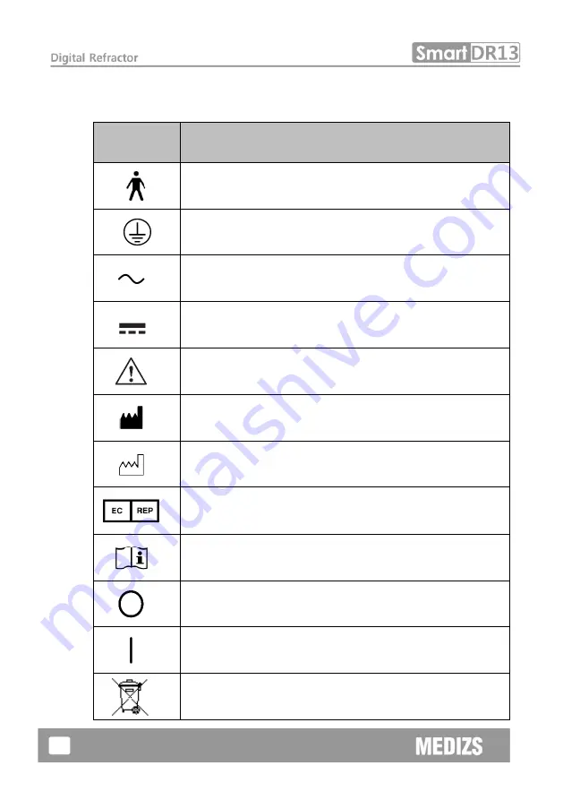
Symbols marked on the instrument 

Symbol 

Description 


Type B 

  Applied Part (Forehead rest)


Protective earth (ground) 


Alternating Current


Direct Current 


Caution


Manufacturer 


Date of Manufacture 


Authorized  Representative  in  the  European 
Community 


Follow Operating Instructions 


Power off (separated with power source)


Power on (connected with power source)


Do not throw away the waste to inappropriate place


Summary of Contents for Smart DR13

Page 1: ......

Page 2: ...ZS Inc takes no responsibilities of the results caused by default omission or misuse of it MEDIZS Inc reserves the right to modify the product itself or specifications of the product without any prior...

Page 3: ...eral safety information 10 3 Note for using the instrument 12 4 Nominations and Functions of Each Parts 13 4 1 Front side of Body 13 4 2 Back side of Body 14 4 3 Control Pad iPad App 15 4 4 Junction B...

Page 4: ...Defined Basic Program 47 9 1 1 Adjustment of the SPH CYL AXIS Value Right 48 9 1 2 Red Green Balance Test for Monocular 50 9 1 3 Cross Cylinder Test with Dots Chart AXIS 51 9 1 4 Cross Cylinder Test w...

Page 5: ...st 63 10 4 Jackson Cross Cylinder Test 64 10 5 Dual Cross Cylinder Test 65 10 6 Horizontal Maddox Rod Test 66 10 7 Vertical Maddox Rod Test 67 10 8 Binocular Balance Test at Polarized Light 68 10 9 Po...

Page 6: ...Negative Relative Accommodation Test 88 10 22 Positive Relative Accommodation 89 10 23 Positive Relative Convergence 90 10 24 Near Vision with Addition 91 10 25 Near Addition Test using Cress Grid Ne...

Page 7: ...y tapping the control of iPad Application which has auto functions of DR 13 Basic components of DR 13 are Refractor body iPad App and junction box In the body of DR 13 there are more than 100 lenses I...

Page 8: ...ement data from Ref Keratometer SmartRK11 can be applied to DR13 s body automatically without lens operation and App also offers PRESE function that put in lenses including auxiliary lens at once New...

Page 9: ...st Protective earth ground Alternating Current Direct Current Caution Manufacturer Date of Manufacture Authorized Representative in the European Community Follow Operating Instructions Power off separ...

Page 10: ...to you or others CAUTION You can fall into a dangerous situation if you don t care It could lead to a slight wound of you or others or malfunction of this equipment NOTE Significant information about...

Page 11: ...device Appliance coupler or separable plug CAUTION Grounding power cables are put in this equipment Always connect them to the grounded AC socket to reduce electric shock CAUTION The Ref body of DR 13...

Page 12: ...ration or impact away from the equipment It can bring some damage inside or outside of the instrument Please carefully handle the instrument 7 When moving equipment fixes the stage always keep power o...

Page 13: ...following user s manual or explanations on service manual More management is available only to service technician of MEDIZS or who is qualified to be in proportion to that position Be careful not to l...

Page 14: ...s and Functions of Each Parts Basic components of DR 13 are Refractor body iPad App and junction box Explanation about each components and functions are following here 4 1 Front side of Body Fig 1 Fro...

Page 15: ...tor maintains horizontality Forehead Fixing Dial Fasten the patient s forehead to forehead rest with dial LED Turn on when the digital refractor power on VD Test window Confirm the patient s VD Forehe...

Page 16: ...ontrol Pad iPad App Fig 3 Control Pad Application on iPad Buttons or Controllers are changed according to the measurement circumstance For detailed controlling method please refer to explanation of ea...

Page 17: ...16 4 4 Junction Box Name Description Power switch Switch for turning power ON and OFF Body Connector Connect with DR13 body Power Connector Power supply connector...

Page 18: ...s application onto your iPad 7 Before running App turn Bluetooth on From home screen choose Setting Bluetooth 8 In a while Bluetooth name of DR 13 appears on the screen and pair DR 13 with iPad 9 Run...

Page 19: ...Chart View the list of patient s information and also search for the information of specific patient Registration Register new clients Operation controller Appear screen to control DR 13 You can choo...

Page 20: ...sh box button you can delete data and It is possible to amend data on detail screen by clicking each line In case schedule of next visit is within one week the date is blue color if it is the day its...

Page 21: ...nts of previous prescription present prescription RK data and LM data By clicking on Read More button as Fig 7 you can see detail information of customer and amend them Also when you left and right sl...

Page 22: ...21 Fig 7 Detail Information View of Client 6 3 Registration In registration you can add information of new visiting clients such as the name age picture and so on Fig 8 Registration of new client...

Page 23: ...splay UI of controller depends on your preference of Digital or Manual Go to Set PAGE 4 Display UI and tap the check box For each controller refer to article 7 to 9 Fig 9 Display UI of Digital type Fi...

Page 24: ...erences to control DR 13 Set Program You can view pages to set and modify the program For method to do that refer to of 6 5 2 Device Bluetooth You can view a page to setting Bluetooth devices of RK 11...

Page 25: ...eter value setting menu is composed of total 4 pages Setting value on each page is as below Fig 12 Parameter setting 1 page 1 Set variation step of SPH CYL AXIS 2 Set the display of CYL as or 3 Set th...

Page 26: ...ent Fix 3 Cross cylinder type on Clock Dial when selecting the chart 4 Set lens diopter for retinoscopy 5 Set additional diopter to input 10D BI separation prism 6 Prism display 7 Blur Break Recovery...

Page 27: ...et whether input Worth 4 Dots inspection result or not 3 Input Stereo value 4 Input Coincidence value 5 Fogging value on both eyes balance test 6 Fogging value on Red Green test 7 In case print prescr...

Page 28: ...27 Fig 15 Parameter setting 4 page 1 Digital Manual mode 2 Beep sound 3 Time display 4 Date Display 5 CP Multi connection 6 Set the inspection Help guide on controller screen 1 2 3 4 5 6...

Page 29: ...tration screen there is list of A E each program set Each program set has a chart and auxiliary lens and another option If select relevant program the page will be changed to screen that can set detai...

Page 30: ...an delete selected program After setting can move to previous page by button which is located in left upper end Bluetooth Setting This page sets Bluetooth connection of each DR CP RK If our device con...

Page 31: ...rmation setting On Basic information setting display you can see A S engineer information and input data of optician s shop or clinic information where is using this machine Fig 18 Basic information s...

Page 32: ...nspection Help List for DR 13 Fig 19 Help Guide Screen In Inspection Help Guide there are visual testing guides for each inspection Tap the Controller View button on the left side and then you can vie...

Page 33: ...32 Fig 21 Controller View Screen...

Page 34: ...o adjust basic data such as SPH CYL and AXIS tap the button among S C or A Then adjust the value by tapping button on the lower right end of operation panel This Plus steps of adjusting value can be s...

Page 35: ...control PD value You can check changing PD values of DR 13 s body while you touch the slide point on the bottom of R L or B and drag it To set the value you must tap the SET button If you tap the X bu...

Page 36: ...ected and you print testing result from RK 11 a numbered badge appears on the upper right icon on the operation panel screen When you tap the icon you can see received data from RK 11 and type the pat...

Page 37: ...36 Fig 25 List View and Detailed View Received data...

Page 38: ...ata touch the button on bottom right side of screen Then bellow pop up appears on the screen If the testee is first visitor touch New Person button and input that testee s information If you have the...

Page 39: ...ppears on bottom right side of the screen After finishing subjective test by DR 13 you can check the prescription for current testee Touch empty space on upper side of OP area with one finger and slid...

Page 40: ...u can control the Chart Projector by operation control Basically you can select the chart images by tapping each image which appears on the screen or by tapping right and left and top and bottom side...

Page 41: ...ual mode that can deliver realistic experience to operators who previously use only manual phoropter and unfamiliar with digital refractor On this article you can learn methods of controlling data on...

Page 42: ...ng the wheel with sphere wheel or aperture control button on both sides Moving strong sphere control is available by tapping upper or lower side of aperture control lens button Control CYL You can con...

Page 43: ...er tapping prism lens window and then tapping upper or lower side of prism button BU BD mode or BI BO mode can be changed by tapping lens window while the lens still set Control Jackson Cross cylinder...

Page 44: ...43 Fig 31 Set the Risley prism left and the Jackson cross cylinder Right...

Page 45: ...of aperture control and then the auxiliary lens window appears Operation penal of CP appears when you tap the triangle shaped button on the lower side If you tap the button again the operation penal w...

Page 46: ...45 Fig 33 Pop up selecting Auxiliary lens and CP Operation penal...

Page 47: ...46 8 3 Open the Manu Bar Manu bar is hidden at the lower side for using wider screen If you tap the both sides of the bottom the menu bar appears or disappears Touchin g Area...

Page 48: ...Start System Defined Basic Program Power on the junction box of DR 13 and wait until the system initialization is over When you check the Bluetooth connection on iPad App tap the operation panel icon...

Page 49: ...and the test of right eye is started To adjust SPH fit for the patient s statue you can tap button or turn the dial on the lower right end of operation panel or swipe up and down over the right or lef...

Page 50: ...49 Fig 35 Adjustment of the SPH CYL AXIS Value...

Page 51: ...letter does he sees more clearly between the letter in green background and red background respectively When he says the letter in green background is clearer turn the dial in direction counterclockw...

Page 52: ...st step SPH CYL AXIS test In case of Jackson Cross Cylinder Test ask the patient with which eye he looks more clearly while pressing number 1 and 2 buttons alternately When he says number 1 turn the d...

Page 53: ...st step SPH CYL AXIS test In case of Jackson Cross Cylinder Test ask the patient with which eye he looks more clearly while pressing number 1 and 2 buttons alternately When he says number 1 turn the d...

Page 54: ...Check the Power of Glasses for Right Eye After the test of right eye is over check again the power of glasses for right eye If necessary use a mask for the test Fig 39 Check the Power of Glasses for R...

Page 55: ...54 9 1 6 Adjustment of the SPH CYL AXIS Value Left 6th step of the System Defined Program is basically to adjust the value of SPH CYL AXIS for left eye Fig 40 Adjustment of the SPH CYL AXIS Value Left...

Page 56: ...icle 9 1 3 Cross Cylinder Test Dots Chart AXIS for a detail explanation Fig 41 Cross Cylinder Test AXIS 9 1 8 Cross Cylinder Test with Dots Chart CYL 8th step of the System Defined Program is to revis...

Page 57: ...step SPH CYL AXIS test Please refer to the article 9 1 9 Red Green Balance Test for Monocular for a detail explanation Fig 43 Red Green Balance Test for Monocular 9 1 10 Check the Power of Glasses fo...

Page 58: ...l Coincidence Aniseikonia Process a test using Horizontal Vertical Unequal Coincidence Aniseikonia chart in the middle of binocular visual acuity test Test Heterophoria following the guidance and do C...

Page 59: ...llowing the guidance Please refer to the article 10 25 Near Distance Addition Test Using Cross Grid Near ADD for detail information Fig 47 Near Distance Cross Grid Test 9 1 14 Near Vision Test with Ad...

Page 60: ...ing the guidance Please refer to the article 10 13 Vertical Von Graefe Test for detail information Fig 49 Near Vertical Von Graefe Test 9 1 16 Near Horizontal Von Graefe Test Test the Near Horizontal...

Page 61: ...60 Fig 50 Near Horizontal Von Graefe Test...

Page 62: ...2 Tap Clock Dial button to change it into distorted vision test mode 3 Tap S button to change it to Spherical Power mode and add Fogging until the line of Clock Dials seen equally 4 Question the pati...

Page 63: ...ng the cylinder axis 2 Tap R or L button to choose the eye for test 3 Tap Clock Dial button to change it into distorted vision test mode 4 Tap C button to change Cylinder Power Mode 5 Turn the dial in...

Page 64: ...en Test Mode 3 Question the patient that which of green and red is seen more clearly or more thickly and check whether both of them are seen equally 4 If red one is seen more clearly or both of them a...

Page 65: ...case a corrected vision is low ask him to read the bigger letter on the upper side 10 4 Jackson Cross Cylinder Test Purpose Subjective test revise maximum circumference refractive power and axis for...

Page 66: ...Dot Group Chart must be seen equally Operation Sequence 1 Tap R or L button to choose the eye for test 2 Tap Dot Group Chart to move on to Cross Cylinder Mode 3 Select the option control tap and tap...

Page 67: ...must be united Operation Sequence 1 Tap Maddox Chart to choose Horizontal Maddox Rod Test Mode 2 At this time tap Horizontal Prism button to change it into Horizontal Maddox Rod Test Mode 3 Turn the d...

Page 68: ...right eye must be united Operation Sequence 1 Tap Maddox Chart to choose the Horizontal Maddox Rod Test Mode 2 At this time tap Vertical Prism button to change it into Vertical Maddox Rod Test Mode 3...

Page 69: ...ized Light Mode 2 Tap B the Binocular button to open Binocular field and add Fogging to about 0 5D and then loosen the interrupted accommodation 3 Ask the patient which line between the upper and lowe...

Page 70: ...lower line seen with the left eye must be seen equally well In addition to in the upper line seen with the right eye the letters in red and green background respectively must be seen as the same as we...

Page 71: ...0 If the lower line is seen clearly tap L and turn the dial counterclockwise direction to increase the value of the left side SPH 11 Repeat this until both of upper and lower lines are seen clearly 10...

Page 72: ...dots and 2 dots appear alternatively it is alternative suppression of right left eye Chart shape Meaning Description Fusion 2 green dots on left right side 1 red dot upside and the dot bottom side are...

Page 73: ...On the left side External Heterophoria Turn the dial counterclockwise direction to increase BI prism until the cross located in the center of circle On the right side Internal Heterophoria Turn the d...

Page 74: ...a Turn the dial counterclockwise direction to increase BI prism until the cross located in the center of circle Left Hyperphoria Press vertical prism button and turn the dial clockwise direction until...

Page 75: ...er the vertical bars are located as one straight line If the answer is yes there is no heterophoria If the answer is no it is heterophoria 3 In case of heterophoria ask the patient which vertical bar...

Page 76: ...izontal bars are located as one straight line If the answer is yes there is no Heterophoria If the answer is no it is Heterophoria 3 In case of Heterophoria ask the patient whether the right bar is hi...

Page 77: ...ient whether he can see the square and dot and if yes ask whether upper lower half of square are arranged straightly In case that the upper half of square is more on right side than the lower half of...

Page 78: ...niseikonia chart to enter horizontal Heterophoria mode 2 Ask the patient whether he can see the square chart if yes ask whether that up down side of square chart is arranged straightly If the left hal...

Page 79: ...tion to enter Heterophoria mode 2 Ask the patient Does it seem like a cross If the answer is Yes there is no Heterophoria Test done If the answer is No it is Heterophoria Go on to the next test 3 Star...

Page 80: ...yperphoria Turn the dial clockwise to increase BU prism When the cross is seen well finish the test Located downside Right Hyperphoria Turn the dial counterclockwise to increase BD prism When the cros...

Page 81: ...ht Hypophoria 3 On vertical prism mode turn the dial clockwise until the horizontal bar came on middle of vertical bar Right Hyperphoria Left Hypophria 4 On vertical prism mode turn the dial countercl...

Page 82: ...the answer is Yes there is no Heterophoria Test done If the answer is No it is Heterophoria Go on the next test 3 Start with horizontal Heterophoria Ask the patient as following 4 Does the shape loca...

Page 83: ...82 Located downside Right Hyperphoria Turn the dial counterclockwise to increase BD prism When the cross is seen well finish the test...

Page 84: ...ape Right Hyperphoria 4 Press BDBU Turn the dial until the horizontal cross chart becomes a cross shape Esophoria Right Hyperphoria 5 Correct the horizontal heterophoria like 1 and correct the vertica...

Page 85: ...84...

Page 86: ...rs with the fixation as a center from 12 to 3 6 and 9 o clock direction clockwise All the bars look like flat including central fixation The patient does not have the capability of stereo vision Press...

Page 87: ...n controller to enter the near point convergence test mode 2 Adjust the location of near point chart as the patient can verify it 3 Moving near vision chart or ballpoint pen close to the patient find...

Page 88: ...eration sequence 1 Press ADD VA button and press NPA button on option controller to enter near point of accommodation test mode 2 Adjust the location of near point chart as the patient can verify it 3...

Page 89: ...ht and binocular Operation sequence 1 Press ADD VA button 2 Adjust the location of near vision chart as the patient can verify it 3 Press R B L button to select the eye for test 4 On option control sc...

Page 90: ...REAK and RECOVERY for left right and binocular Operation sequence 1 Hang near vision chart on the bar 2 Change SPH value and search the blurred point 3 After finding blurred point press ADD VA button...

Page 91: ...on sequence 1 Select horizontal Von Graefe chart and then adjust X value to search blurred point 2 After finding blurred point touch PRC button on option controller and then input the value on Blur an...

Page 92: ...Lens None Objective Test the Near Vision with Addition for left right and binocular Operation Sequence 1 Press R B L buttons to select the eye for test 2 Press ADD VA button Lower the Near Vision Cha...

Page 93: ...equally similar with Far Vision Cross Grid Test Operation Sequence 1 Press ADD button to drop the Near Vision Cross Grid chart at the place of about 40cm 2 Press R B L button to select the eye for tes...

Page 94: ...and Maintenance If any problems that you cannot solve has caused please contact the selling distributor Referring name plate or system information on setup menu please note below information to the d...

Page 95: ...ons calibration instructions or other information will be provided to assist service personnel to repair parts of the equipment that are designated by MEDIZS as repairable by service personnel 3 Dispo...

Page 96: ...use volatile object thinner or benzene etc Polish each part with a dry cloth containing detergent solution 5 Environmental requirements Operation 10 to 40 oC 30 to 75 r h 70 to 106 kPa Storage Transpo...

Page 97: ...0 25 Dual Cross Cylinder Lens Retinoscope 1 5D 2 0D Auxiliary Lenses Pin Hole Lens 2mm Moddox Rod Right eye Red Horizontal Left eye Red Vertical Red Green Filter Right eye Red Left eye Green Polarizi...

Page 98: ...97 13 Components Description Quantity 1 Forehead Pedestal 1 2 Near Vision Chart 1 3 Near Vision Stick 1 4 Screw bolt 2 5 Screw cap 2 6 Fuse 1 7 Data cable 1 8 Power Cable 1...

Reviews: