Multitest 0.5dV, 1dV & 2.5dV
Service and Repair Manual
Number 022-780
Issue Number: 02
Page 10 of 32
8. Motor Replacement
26.
Remove the base plate as per 4, Instructions 1 to 5
27.
The motor/gearbox unit, complete with an
encapsulated encoder (also known as the
‘tachometer’), is attached to the base
casing via a mounting plate retained with 3-
off M6 x 12 cap head screws.
28.
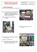
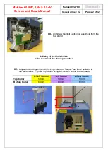
Locate the motor as identified in the
photograph
29.
Remove the Transformer as per
Section 5.
30.
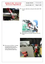
Remove the motor red/black connections to
the VIC PCB:
Red from J11, Black from J10.
31.
Record the connections before removing -
refitting the wrong way round will cause
stand to go in reverse direction.


