


P070/P071/P085/P086/P100/P101
6-4
6
Attachments
2
1
1
2
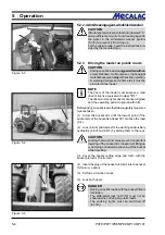
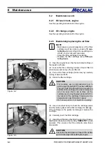
Figure 6-7
Figure 6-8
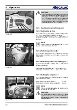
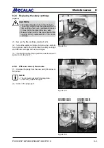
Figure 6-9
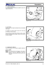
(3) Pick up the bucket using the quick-change device and,
by simultaneously tilting the quick-change device, raise the
bucket until the quick-change device is next to it (6-7).
(4) Lock the bucket with the pilot valve for the auxiliary
hydraulics (4-8/5).
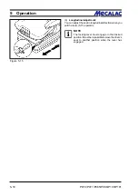
(5) Check that the device is mounted and locked correctly
on both sides.
DANGER
The two bolts of the quick-change device must be
in the bore holes of the bucket suspension and
must be clearly visible (6-8/arrow).
(6) Shut down the engine.
(7) Depressurise the hydraulic lines. For this purpose,
move the pilot valve for the auxiliary hydraulics (4-8/5) back
and forth several times.
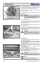
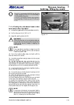
(8) Pull off the protective caps from the hoses of the quick-
change device (6-9/1).
(9) Swing up the protective flaps of the quick-change
couplings on the multi-purpose bucket (6-9/2) and connect
them with the hoses of the quick-change device (6-9) by
tightly pushing them in.
CAUTION
When making connections, make sure that the
hydraulic ports are clean and completely con-
nected.
Dismounting
(1) Place the multi-purpose bucket firmly on the ground.
(2) Shut down the engine.
(3) Depressurise the hydraulic lines. For this purpose,
move the pilot valve for the auxiliary hydraulics (4-8/5) back
and forth several times.
(4) Disconnect the quick-change couplings on the multi-
purpose bucket from the hoses of the quick-change device
by pulling firmly.
(5) Fit the protective caps on the hoses of the quick-
change device (6-9/1).
(6) Start the engine and unlock the bucket:
Press the release button for the quick-change device
(4-8/11) and unlock the bucket with the pilot valves for the
auxiliary hydraulics (4-8/5).
(7) Further dismounting is in the reverse order.
CAUTION
The hydraulic quick-change device must only be
locked
when an attachment has been mounted.
NOTE
The type plate is on the rear of the bucket, on the
right-hand side beneath the cross arm.
Summary of Contents for AX 1000
Page 9: ...Safety regulations...
Page 21: ...Signs...
Page 24: ......
Page 25: ...Protectionagainsttheft...
Page 28: ......
Page 29: ...Description...
Page 43: ...Operation...
Page 53: ...Attachments...
Page 58: ......
Page 59: ...Rescue towing lashing lifting by crane...
Page 66: ......
Page 67: ...Maintenance...
Page 83: ...Faults causes and remedies...
Page 86: ......
Page 87: ...Circuit diagrams...
Page 97: ......
Page 100: ......
Page 101: ...Technical data loader...
Page 111: ...Technical data attachments...
Page 124: ......
Page 125: ...Additional options modifications Notes on inspection for loaders...
Page 127: ...P070 P071 P085 P086 P100 P101 13 3 Additionaloptions modfications 13...
Page 128: ...P070 P071 P085 P086 P100 P101 13 4 13 Additionaloptions modfications...
Page 129: ...P070 P071 P085 P086 P100 P101 13 5 Additionaloptions modfications 13...
Page 130: ...P070 P071 P085 P086 P100 P101 13 6 13 Additionaloptions modfications...
Page 131: ...P070 P071 P085 P086 P100 P101 13 7 Additionaloptions modfications 13...
Page 132: ...P070 P071 P085 P086 P100 P101 13 8 13 Additionaloptions modfications...
Page 133: ...P0700 P0710 P0850 P0860 P1000 P1010 Index i Index...
Page 134: ...P0700 P0710 P0850 P0860 P1000 P1010 Index ii Index...
Page 135: ...P0700 P0710 P0850 P0860 P1000 P1010 Index iii Index...
Page 136: ...P0700 P0710 P0850 P0860 P1000 P1010 Index iv Index...
Page 137: ...P0700 P0710 P0850 P0860 P1000 P1010 Index v Index...
Page 138: ...P0700 P0710 P0850 P0860 P1000 P1010 Index vi Index...
Page 139: ...P0700 P0710 P0850 P0860 P1000 P1010 Index vii Index...
Page 140: ...P0700 P0710 P0850 P0860 P1000 P1010 Index viii Index...
Page 141: ...P0700 P0710 P0850 P0860 P1000 P1010 Index ix Index...
Page 142: ...P0700 P0710 P0850 P0860 P1000 P1010 Index x Index...
Page 143: ...P0700 P0710 P0850 P0860 P1000 P1010 Index xi Index...
Page 144: ...P0700 P0710 P0850 P0860 P1000 P1010 Index xii Index 23128003 Index 0...


