P070/P071/P085/P086/P100/P101
5-5
Operation
5
(7) Release the parking brake (4-9/3).
(8) Preselect hydraulic drive stage II (4-10/9).
(9) Select the travel direction (4-10/11).
(10) Press the accelerator pedal (4-8/8).
NOTE
- The loader starts. The travel speed is determined
by the position of the accelerator pedal.
- The service brake is activated by depressing
the brake pedal (4-8/11).
DANGER
Changing the travel direction during driving is
not
allowed to avoid any danger to other road users.
5.2.4
Working with the loader
Generally, all work is carried out in hydraulic stage II
(4-10/9).
For special tasks which ask for a more sensitive control of
the speed or a higher engine speed at reduced travel
speed, hydraulic drive stage *I“ (4-10/9) can be selected.
The travel speed can thus be reduced to 7 km/h.
To attain full performance, the combined action of propul-
sion and of the working hydraulics is necessary. It is up to
the operator to control the available power using the
accelerator, the inching function and the hand lever for the
working hydraulics.
NOTE
The hydraulic drive stage can be switched from
I to II or vice versa while driving. However,
switching from drive stage II to I is not recom-
mended when driving at high speeds since the
loader is then braked very abruptly.
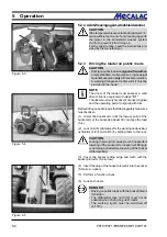
(1) Lock both doors.
(2) Release the parking brake (4-9/3).
(3) Preselect hydraulic drive stage (4-10/9).
(4) Select the travel direction (4-10/11).
(5) Press the accelerator pedal (4-8/8).
NOTE
- The travel speed and the thrust force are altered
exclusively by depressing the accelerator pedal.
- When driving up gradients, the travel speed
decreases in spite of full throttle in favour of the
thrust force.
- The thrust forces and travel speeds are the
same in the forward and the reverse direction.
Summary of Contents for AX 1000
Page 9: ...Safety regulations...
Page 21: ...Signs...
Page 24: ......
Page 25: ...Protectionagainsttheft...
Page 28: ......
Page 29: ...Description...
Page 43: ...Operation...
Page 53: ...Attachments...
Page 58: ......
Page 59: ...Rescue towing lashing lifting by crane...
Page 66: ......
Page 67: ...Maintenance...
Page 83: ...Faults causes and remedies...
Page 86: ......
Page 87: ...Circuit diagrams...
Page 97: ......
Page 100: ......
Page 101: ...Technical data loader...
Page 111: ...Technical data attachments...
Page 124: ......
Page 125: ...Additional options modifications Notes on inspection for loaders...
Page 127: ...P070 P071 P085 P086 P100 P101 13 3 Additionaloptions modfications 13...
Page 128: ...P070 P071 P085 P086 P100 P101 13 4 13 Additionaloptions modfications...
Page 129: ...P070 P071 P085 P086 P100 P101 13 5 Additionaloptions modfications 13...
Page 130: ...P070 P071 P085 P086 P100 P101 13 6 13 Additionaloptions modfications...
Page 131: ...P070 P071 P085 P086 P100 P101 13 7 Additionaloptions modfications 13...
Page 132: ...P070 P071 P085 P086 P100 P101 13 8 13 Additionaloptions modfications...
Page 133: ...P0700 P0710 P0850 P0860 P1000 P1010 Index i Index...
Page 134: ...P0700 P0710 P0850 P0860 P1000 P1010 Index ii Index...
Page 135: ...P0700 P0710 P0850 P0860 P1000 P1010 Index iii Index...
Page 136: ...P0700 P0710 P0850 P0860 P1000 P1010 Index iv Index...
Page 137: ...P0700 P0710 P0850 P0860 P1000 P1010 Index v Index...
Page 138: ...P0700 P0710 P0850 P0860 P1000 P1010 Index vi Index...
Page 139: ...P0700 P0710 P0850 P0860 P1000 P1010 Index vii Index...
Page 140: ...P0700 P0710 P0850 P0860 P1000 P1010 Index viii Index...
Page 141: ...P0700 P0710 P0850 P0860 P1000 P1010 Index ix Index...
Page 142: ...P0700 P0710 P0850 P0860 P1000 P1010 Index x Index...
Page 143: ...P0700 P0710 P0850 P0860 P1000 P1010 Index xi Index...
Page 144: ...P0700 P0710 P0850 P0860 P1000 P1010 Index xii Index 23128003 Index 0...

