


IM 685 / Page 25
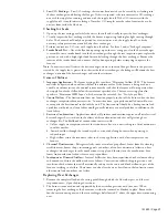
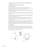
Combination Fan and Limit Control
The fan limit control is a hydraulic action type with a remote sensing element and connecting capillary
tube. The sensing element is locked into a bracket located on one of the heat exchanger tubes about
halfway toward the back of the furnace, on the side away from the blower. One corner of the bracket is
bent aside to remove the element.
Normal setting of the FAN control: Fan On=125
°
F., Fan Off=100
°
F.
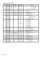
The LIMIT control must never be set higher than the temperature listed below. If the burner is shutting
off on high limit at these settings it indicates that there is a problem with the furnace not getting
enough air or it is being overfired.
Table 4. LIMIT control set points
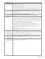
Maintenance
Preventative maintenance is the best way to avoid unnecessary expense and inconvenience. The system
should be inspected at regular intervals by a qualified service technician. The service intervals below are
typical for average situations but will have to be adjusted to suit the particular circumstances.
Fuel pressure settings, control settings, and linkage adjustments should only be made by persons
thoroughly experienced with the burner and control system and should not be tampered with by
persons without such experience.
Always replace covers on burner controls and boxes as the electrical contacts are sensitive to dust and
dirt. Maintenance of flame safeguard, controls, gas valves, and other such components should be
performed in accordance with instructions contained in the manufacturer’s bulletins.
Monthly
1. Check air filters and main supply fan drives, replacing if required.
2. Check flame signal with a keyboard display module or a DC voltmeter.
Twice Yearly
1.
Burner Air –
Check burner fan wheel for dirt build-up and lint. Check combustion air intake louver
and flue box for dirt buildup and accumulation of windborne debris.
2.
Cleaning –
Inspect flue tubes and combustion chamber, cleaning as required. Keep burner vestibule
clean. Dirt and debris can result in burner air blockages.
Yearly
1.
Gas Train –
Check all valves, piping, and connections for leakage. Remove burner gun assembly.
Inspect, and if required, clean the flame rod, ignition electrode, main burner disc, and blast tube.
Check tightness of linkage fasteners and bolts that could work loose from vibration and movement.
2.
Combustion –
Check quality of combustion. Test CO
2
and CO and look for irregularities in fire
shape. If combustion characteristics have changed since the last test, determine the cause. Changes in
input, changes in the BTU content of gas being supplied, reduced combustion air due to dirty
blower wheel, or flue passages in need of cleaning can all cause changes in CO
2
reading. When a
readjustment seems necessary, do not make the adjustment without first trying to determine if the
required change is not an indication that something else is in need of correction.
3.
Flame Safeguard –
Perform a flame failure check and "pilot" turndown test. See control
manufacturer’s bulletin for further information.
4.
Motor –
Motor life will be increased by proper oiling. There are provisions in both end shields for
relubrication. Re-oil each bearing with 150 drops (approximately 1 teaspoon) SAE-20 oil.
5. If the burner is to be out of service for the summer, turn off the burner control switch and close the
manual gas cocks.
BURNER
LIMIT CONTROL
BURNER
LIMIT CONTROL
MODEL
SET POINT
MODEL
SET POINT
020
215
079
181
025
160
080
229
032
196
100
170
040
154
110
222
050
229
140
168
064
185
150
194
065
232
200
151


