

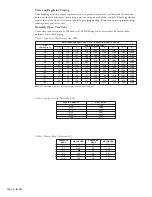


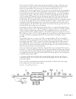
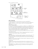


Page 18 / IM 685
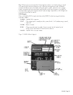
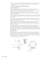
Air and Gas Control Linkage
An L-shaped control rod is connected to the actuator and passes through the burner housing and into
the control box. This control rod positions the valves that control the burner air and gas, and actuates
switches in the control box to prove when it is at the maximum and minimum position. When the
actuator positions the control rod to the minimum rate position, the bracket on that rod that connects
to the air valve and gas valve should be firmly bottomed against the end of the gas valve which acts as its
stop. The linkages to the air and gas valve should be straight and in alignment. Although the bracket is
to bottom out, the plate connected to it which slides from right to left to control airflow should slide
freely and not be forced against either the right or left side member of the air box.
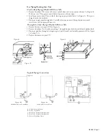
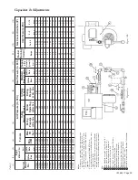
At the minimum rate position maintain a gap according to dimension "D", Figure 10a. With that
sliding plate in this minimum rate position, check dimension "E", Figure 10a. To gauge opening "E",
use a drill blank held perpendicular to the plate. For Models 050-200 opening "E" can be accessed
through the grommeted opening in the primary air collector. See (3), Figure 10a. For Models 020-040
the primary air collector must be removed. Generally, it is easier to remove the collector with the
1
⁄
2
inch
diameter tube still attached by disconnecting the tube at the other end.
At the maximum rate position the sliding blade should be full open, but it should not be forced against
the left side piece of the air box.
The control rod bracket that connects the air and gas valves must be correctly positioned on the control
rod such that the bracket will be firmly held under tension against its stop when the actuator is in the
minimum rate position, and so the sliding blade will open fully without making contact at the end of
the stroke. When modulating towards the minimum rate position the actuator will continue to travel
after the bracket contacts the stop, flexing the vertical end of the control rod so the bracket is held under
tension. To correctly locate the bracket on the rod, first adjust the air damper linkage so there will be a
gap per dimension "D", Figure 10a, when the bracket is bottomed out against the end of the valve.
Second, loosen both set screws on the bracket assembly so the bracket is free to slide on the rod. Third,
position the actuator to the maximum rate position. Position the sliding blade to the wide open
position. Grasp the rod and while applying some thrust to the rod in the direction of the actuator to
take up any free play, and with the bracket in alignment with the linkages that connect to it, tighten the
two set screws. Return the actuator to the minimum rate position.
The adjustable plate (2), Figure 10a is positioned to provide an opening per dimension "F".
Figure 10. Air and Gas Control Linkage
Figure 10b.
Figure 10a.
l
e
d
o
M
*
*
*
T
H
D
E
F
G
0
2
0
5
0
0
.
6
1
1
.
0
0
5
.
0
3
.
3
5
2
0
5
0
0
.
5
2
1
.
0
3
8
.
0
3
.
3
2
3
0
5
0
0
.
0
5
1
.
6
0
.
1
0
3
.
3
0
4
0
5
0
0
.
1
6
1
.
5
2
.
1
0
3
.
3
0
5
0
0
2
0
.
9
9
0
.
5
2
.
1
0
3
.
3
4
6
0
0
2
0
.
6
3
1
.
0
6
.
1
0
3
.
3
5
6
0
0
2
0
.
6
3
1
.
0
6
.
1
0
3
.
3
9
7
0
0
2
0
.
6
0
1
.
8
8
.
1
0
3
.
3
0
8
0
0
2
0
.
6
0
1
.
8
8
.
1
0
3
.
3
0
0
1
0
2
0
.
0
1
1
.
4
4
.
2
0
3
.
3
0
1
1
0
2
0
.
6
3
1
.
5
0
.
1
8
2
.
4
0
4
1
0
2
0
.
6
3
1
.
0
3
.
3
8
2
.
4
0
5
1
0
2
0
.
0
4
1
.
0
3
.
3
8
2
.
4
0
0
2
0
2
0
.
0
4
1
.
0
5
.
4
8
2
.
4


