IM 676
41
7. After compressor lockout timer TD1 has timed out, start the system by moving pumpdown
switches PS1 and PS2 to “auto pumpdown” position.
8. After running the unit for a short time, check the following:
§
Oil level in each compressor crankcase
§
Rotation of fans
§
Flashing in refrigerant sightglass.
9. Verify superheat temperature is at the factory setting of 8 to 12 degrees F (4.4 to 6.7 degrees C).
10. After system performance has stabilized, complete the “Compressorized Equipment Warranty
Form” (Form No. 415415Y) to obtain full warranty benefits. Return the form to McQuay
International through your sales representative.
Sequence of Operation
The following sequence of operation is typical for ALR SeasonPak air-cooled water chiller, Models
ALR 032E through ALR 185E (items in italics apply only to Models ALR 080E through 185E).
The sequence varies depending upon options.
Start - up
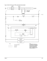
With the control circuit power on and the control stop switch S1 closed, 115V power is applied
through the control circuit fuse F1 to the compressor crankcase heaters HTR1 and HTR2 (HTR3 and
HTR4), the compressor motor protections MP1 and MP2 (MP3 and MP4), and the primary of the
24V control circuit transformer. The 24V transformer provides power to the contacts of the low
pressure controls LP1 and LP2 and the compressor lockout timer TD1 and TD2.
When the remote time clock or manual shutdown switch turns on the chilled water pump, the
flow switch closes and 115V power is applied to the relay contacts on the leaving water control
LWC1. The unit will automatically operate in response to the LWC1 if the manual pumpdown
switches PS1 and PS2 are closed ( in the “auto” position); the compressor lockout time relays R5
and R6 (R7 and R8); and the freezestats FS1 and FS2, high pressure controls HP1 and HP2, and the
compressor motor protectors MP1 and MP2 (MP3 and MP4) do not sense failure conditions.
On a call for cooling, the leaving water control LWC1 completes the circuit to the liquid line
solenoid valve SV1 for refrigerant circuit #1, opening the valve and allowing refrigerant to flow
through the expansion valve and into the evaporator. As the evaporator refrigerant pressure
increases, the low pressure control LP1 closes. This energizes the compressor starting relay R9,
starting the compressor via the compressor contactors M1 and M5. Closing the R9 contacts also
energizes the condenser fan motor contacts M11 and M12 starting the fan motors.
As additional stages of cooling capacity are required, the leaving water control LWC1 energizes
the liquid line solenoid valve SV2 of the refrigerant circuit #2. After the compressor sequencing
time delay TD11 has closed, the same starting sequence is initiated in refrigerant circuit #2.
If still more cooling is required, the leaving water control will start the remaining compressors
and then de-energize unloader solenoids until the capacity requirement is met.

