40
IM 676
Start-up and Shutdown
Pre Start-up
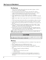
1. Open all electric disconnects and check all electric connections for tightness. Check all
compressor valve connections for tightness.
2. Inspect all water piping for flow direction and correct connections at the evaporator.
3. Verify thermostat water temperature sensor is installed in the leaving water line (supply to
building). On all ALR units the sensor well and sensor are factory mounted.
4. Check compressor oil level. The oil level should be visible in the oil sightglass.
5. Check voltage of the unit power supply and make certain voltage is within
±
10% of nameplate
rating.
6. Check unit power supply wiring for proper ampacity and a minimum insulation temperature of
75
°
C.
7. Verify all mechanical and electrical inspections have been completed according to local codes.
8. Verify all auxiliary control equipment is operative and an adequate cooling load is available.
9. Open compressor suction and discharge shutoff valves until backseated. Always replace valve
seal caps.
10. Open control stop switch S1(off) and place pumpdown switches PS1 and PS2 on “manual
pumpdown,”. Turn on the main power and control disconnect switches. This will energize
crankcase heaters. Wait at least 12 hours before starting up unit.
11. Open all water flow valves and start the chilled water pump. Check all piping for leaks and
vent the air from the evaporator as well as from the system piping. Flush the evaporator and
system piping to obtain clean, noncorrosive water in the evaporator.
NOTE: If LWC1 is a Unit 33 Metasys control, the control must be energized before the
chilled water flow switch is closed.
CAUTION
Most relays and terminals in the unit control center are energized with S1 and the control
circuit disconnect on. Do not close S1 until start-up.
Start-up
1. Verify compressor suction and discharge shutoff valves are backseated. Always replace valve
seal caps.
2. Open oil equalization line valve (ALR 080E through 185E only).
3. Open manual liquid line shutoff valve at the outlet of the condenser subcooler.
4. Set temperature controller LWC1 to the desired chilled water temperature. Set the control
band.
5. Start auxillary equipment by turning on the following:
§
Time clock
§
Ambient thermostat and/or remote on/off switch
§
Chilled water pump.
6. Verify pumpdown switches PS1 and PS2 are in “manual pumpdown” (open) position. If
pressures on the low side of the system are above 60 psig (414 kPa), the unit will start and
pump down.

