38
IM 676
Unit Layout and Principles of Operation
Figure 10, Major component locations
The figure below illustrates component locations for each unit size.
Control Center
All electrical controls are enclosed in a weatherproof control center with keylocked, hinged access
doors. The control center has two separate compartments, high voltage and low voltage. All high
voltage components are located in the compartment on the right side of the unit.
The low voltage components are located on the left side with the live terminals behind the
deadfront panel. This protects service personnel from live terminals when accessing the adjustable
and resettable controls.
Control center layouts
ALR 032E through 75E
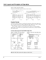
Figure 11, Left side, 115V control section
Figure 12, Right side, high voltage power
section
Note: PB1, PB2, PB3 are used with multiple point power wiring

