52
AGZ 035A through 065A
IOMM AGZ-3
MicroTech Controller Installation and Operation
All operational descriptions are based on the MicroTech controller software versions AGZ2E01A.
Operating characteristics and menu selections can vary with other versions of software. Contact
McQuay Technical Support for software update information.
General Description
The MicroTech control panel contains a model 250-06 microprocessor based controller that provides
all control functions. The operator can review and change operating parameters from the interface
keypad that consists of twelve input keys and a two line by sixteen character display. In addition to
providing all normal operating controls, the controller monitors all equipment protection devices on
the unit and will shut the system down and alarm through a set of dedicated alarm contacts. Important
operating conditions at the time of the alarm are retained in the controller’s memory to aid in
troubleshooting and unit diagnostics. McQuay MicroTech Monitor software is available for remote
adjustment and monitoring of the chiller.
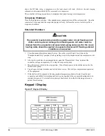
The system is protected by a simple password scheme that allows access by authorized personnel.
The operator must enter a valid password into the panel before any setpoints can be changed.
Optional Sensor Packages
•
Refrigerant Sensor Package
Suction line temperature, circuit #1
Suction line temperature, circuit #2
Liquid line temperature, circuit #1
Liquid line temperature, circuit #2
•
Unit amp package
Unit amperage - Percent total unit amperage including compressors and condenser fans.
Does not include externally powered equipment such as water pumps.
Installation
The MicroTech controller is shipped factory tested with default values for the type of refrigerant. All
control values must be entered for the specific application of the chiller.
Sensors and transducers
Sensors and transducers are mounted and connected to the analog / digital input (ADI) board with
shielded cable. The evaporator and condenser pressure transducers depress the Schrader fittings and
can be replaced without pumping the unit down. The pressure transducers are connected to the
MicroTech analog inputs with IDC connectors (Insulation Displacement Connectors). High pressure
transducers have a red dot and low pressure transducers have a blue dot. Water sensors are in thermal
wells for easy replacement without draining the water system. Optional refrigerant line temperature
sensors are in a copper sleeve brazed to the appropriated refrigerant line.
Control wiring
Low voltage control wiring is installed, labeled and tested by the factory before shipment.
Remote 4-20 milliamp signals
Signals for leaving water reset or demand limit are provided by the installing contractor and
connected to the terminal block as indicated by the unit wiring diagram. See Field Wiring diagram
for details.
Summary of Contents for AGZ 035A
Page 6: ...6 AGZ 035A through 065A IOMM AGZ 3 Figure 3 Clearance Requirements...
Page 18: ...18 AGZ 035A through 065A IOMM AGZ 3 Electrical Legend Figure 8 Electrical Legend...
Page 19: ...IOMM AGZ 3 AGZ 035A through 065A 19 Figure 9 Typical Field Wiring with Global UNT Controller...
Page 21: ...IOMM AGZ 3 AGZ 035A through 065A 21 Figure 11 Single point Connection with FanTrol...
Page 22: ...22 AGZ 035A through 065A IOMM AGZ 3 Figure 12 Single point Connection with SpeedTrol...
Page 23: ...IOMM AGZ 3 AGZ 035A through 065A 23 Figure 13 Unit Control Schematic UNT...
Page 24: ...24 AGZ 035A through 065A IOMM AGZ 3 Figure 14 Staging Schematic UNT...
Page 25: ...IOMM AGZ 3 AGZ 035A through 065A 25 Figure 15 MicroTech Controller Schematic...
Page 26: ...26 AGZ 035A through 065A IOMM AGZ 3 Figure 16 Unit Control Schematic MicroTech...
Page 27: ...IOMM AGZ 3 AGZ 035A through 065A 27 Figure 17 Staging Schematic MicroTech...
Page 94: ...94 AGZ 035A through 065A IOMM AGZ 3 Notes...
Page 95: ......


